Think Metric, Part 3
Insight from several technology suppliers—in design software, mold components, programming, machines, cutting tools and measurement equipment who have been following the metric trend—may help to make the transition a smooth one.
In Part 1 (March, 2013) we presented an argument for designing and building in metric, in Part 2 (April, 2013) we shared feedback from the field on making the metric conversion in your shop after realizing it just makes sense, and in this third installment we will review some insight from a handful of technology suppliers whose products and equipment populate today’s mold manufacturing facilities, and who believe going metric will result in more efficient and profitable moldmaking.
Arsenal of Advice
You are a manager at a modern mold manufacturing company and after watching a CNBC special on the extent of the European tooling market, your owner has an epiphany. He approaches you to say that the company is going all metric, and you have two weeks to make the transition and get up to speed. Questions immediately come to mind. You know you make a great mold in inch, but can you still make a great mold in metric? Where can I go for help?
For some advice, we sought the input of technology suppliers within the areas of mold design and manufacturing software, CNC machining, cutting tools, mold components and measurement equipment. We received responses from several. These companies and many others are willing and able to lend their knowledge and expertise to make the transition to metric smoother, so be sure to discuss this trend with your technology suppliers.
As a side note, the research for this article did uncover some interesting facts that may help with accuracy about which many moldmakers may not be aware.
To make this collection of information easier to follow, it is broken down into each area of responsibility common for mold shops: Design, Mold Components, Programming, Machining, Cutting Tools and Measurement.
1. Design
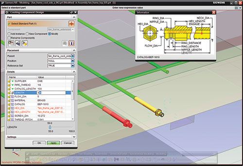
When it comes to design software parameters, Siemens PLM Software Marketing Director Aaron Frankel shares some insight about working with metric design by looking at designers who use Siemens NX. When asked how one sets up the software to work in metric he explains, “At its core, it is a system that automates the mold design process and captures the way the end user wants to work to automate their job. At the setup of each job or project, inches or metric is a selectable option.”
Frankel goes on to review the differences in the set up for inch versus metric, “The user can set and define any parameters at the start, and add additional parameters as they go. We have customers all over the world, so we make sure to support both units.”
When asked if there are major parameters that need to be changed when a designer switches from inch to metric, Frankel says that no major parameters need to be changed. However, he does note a few things a user needs to be aware of when designing in metric after being used to designing in inch, “The automated NX system will convert units as needed. For example, if the project has started in metric, and you want to add a parameter that was designed in inches, everything will convert to the proper unit.”
Also of note is that a design file can be exported in different ways. “The raw data may or may not specify units depending on the file type; however, if you import a file with set units, they will be specified based on the unit of the file that it’s being imported to,” explains Frankel.
Siemens PLM Software does have both inch and metric part catalogs.
ProE user Gary Saperstein offers the following: “ProE doesn't care if it is metric or imperial. Designing in metric is much easier than imperial mainly because no fractions are used. When I was at AMP, the mold design units—if not stated by the buyer—were in the unit of the product design. Then there is the discussion of hard metric versus soft metric (where the size of the part is a nominal inch size converted to metric numbers). And finally, the discussion of Dual dimensioning with what unit is primary and what unit is secondary. ProE handles all scenarios.”
Chris Outlaw, an Engineering Manager at Cavaform uses Solidworks as his design software, and says, “Setting up SolidWorks part files for metric is rather simple. So simple in fact, that it has a toolbar in the lower right side of the application that allows you to toggle to the desired unit system at any point during the design. The drawing files are very easy as well; however, it is better practice to set the drawing up in the desired unit system from the start of the project.”
2. Components
As designers begin to make the change to metric they will need a source for the mold base—standard or custom—as well as other mold components. Standard metric mold base sizes and mold components are available from many companies.
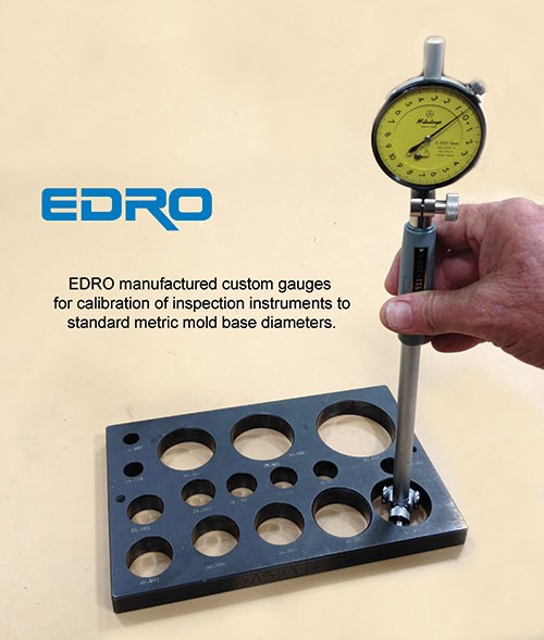
For custom bases EDRO shared how they handle the metric issue. Over the past decade, the company has seen large overseas corporations extending their operations and mold manufacturing to the U.S. through acquisitions and expansion—creating a global mold market. Many of these companies require their molds to be designed and built in metric, especially if the tool will run in another country to allow for local maintenance.
In response to this trend, the company has aligned its operations to produce imperial and metric mold bases side-by-side. Currently metric jobs make up approximately 30-percent of their builds.
As Guy Recendez, EDRO’s Operations Manager describes, “A metric job is handled as a metric job start to finish—no conversion to decimal, which could create errors. We have the setups, programming, tooling, procedures and inspection equipment in metric.”
In addition to complete mold base manufacturing, they also produce a stainless holder steel grade commonly used in mold base applications. Over the years, the company has added certain metric plate thicknesses to its stock program to adapt to the increase in metric mold plate demands.
A unique steel production approach allows for flexible and quick replenishment of both imperial and metric gauges, as well as the ability to quickly produce any custom plate sizes. This allows for less material removal from raw to finish machine sizes, as opposed to achieving a metric plate thickness from the next available imperial gauge size up, according to the company.
HASCO has been supplying metric mold bases and mold components for the plastics industry for decades. Louis Hébert, Managing Director from HASCO Canada explains, “Our mold base sizes are based on the most common injection machine platen sizes. Typically, there would be a minimum of 2 mm clearance per side between the tie bar and the plate edge. All plates can be purchased separately and are fully interchangeable. This gives more flexibility for design. Also, the plates are built with high precision, so reference location for additional CNC machining is easily done.”
Hébert continues to explain that tolerances used are according to the International Standard ISO 286 of systems of limits and fits. “Simply, it is defined as lower case letter and number for shafts and capital case letter and number for holes. The appropriate match of letters and numbers gives a specific fit. As an example, a shoulder bushing inside diameter with H7 tolerance will slide easily into a g6 tolerance leader pin diameter with no play. The bottom line is that you know exactly the tolerance you should use for machining. There is no need to wait until you get the component to get started with machining.”
Hébert also pointed out that in his experience he has more options in metric because increments are tighter. For example ejector pins come in .1mm or 0.0039" versus 1/64 increments or 0.0156". Now pins can come in 0.010" increments, but this shows how the metric system allows for more design options.
3. Programming
CNC programing is a key part of the process to move from design to machining. Perhaps the earlier statement, “with programing software you can easily switch from inch to metric and back” was an oversimplification. To get a real understanding of what is involved, here is input from two CAM software suppliers.
Peter Dickin, Marketing Manager over at Delcam, spoke to one of the company’s engineers and was assured that switching from imperial to metric is a simple change of setting; however, the choice must be made at the start of the project when all the default values appropriate to the chosen system are set.
“It is much more complicated to change mid-project, but this is unlikely to be necessary. Someone could begin a project and then realize mid-way through that they were using the wrong system. In those cases, it would most likely be safer to start over from the beginning even though it is possible in theory to make the change,” explains Dickin.
One trick Dickin shares was the ability to use sizes from the other system during a project. “For example, a U.S. user might be doing a project in inches, but wanted to use an imported cutter that was supplied only in metric sizes. He can simply add mm after the dimension and it will be converted automatically to the equivalent inch dimension.”
Over at Mastercam, Doug Nemeth, Corporate Sales Manager notes, “As a U.S. company with a global presence and with roughly half of our sales coming from overseas, we could estimate that at least half of our users are running in a metric configuration. It can be configured to start up in either metric or imperial units, and users can easily switch between the two in a given session.”
Nemeth continues to explain that in a metric configuration, not only are the units used in metric, but all tool libraries and default settings are also in metric. He says that there is no need for the user to do any conversions to get the metric values they need.
Understanding that some users may need to use metric settings in an imperial environment, they do allow this.
According to Nemeth, they also have some simple, but useful tools to help users quickly convert values from inch to metric and vice versa. “For instance, if a user is in an imperial configuration, but needs to enter a value such as a tool stepover in metric, they only need to type in the metric value followed by ‘mm’. The system will automatically convert the metric value to inches.”
4. CNC Machining
As most CNC machines are built to metric standards in Europe and Japan, it is not surprising that there is a metric option available. Actually, inch is the option; metric is the standard for these machines.
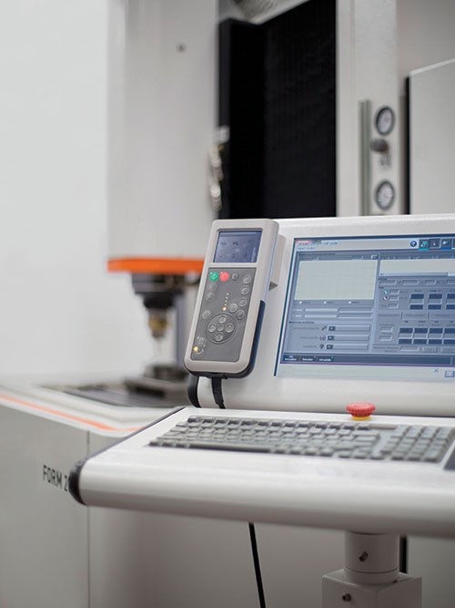
Gisbert Ledvon, Director of Business Development at GF AgieCharmilles agrees that the metric switch is easy with many of today’s machine tools. “For our advanced EDM and high-speed milling machines, the transition from metric to inches and vice versa is basically done with the flip of an electronic switch; and because the capability is essentially a parameter within the machine’s control, shops can make the measurement switch at any time to easily accommodate programs with either metric or inch dimensions. Additionally, our machine controls allow shops to switch languages—for instance from English to Spanish, as well.”
For high-precision mold machining, Ledvon recommends working in metric and refraining from converting dimensions to inch. The reason is that in these applications, shops using metric machine movements eliminate the risk of possibly losing a very small amount of accuracy. For example, dividing all of the numbers by 25.4 to switch from metric to inches can result in rounding that reduces precision by several microns over a meter of machine travel.
In the case of wire for wire EDM machines, machining inaccuracies can result when shops convert wire, which is produced in metric diameters, to inches. To illustrate, wire that is 0.25 mm is actually equivalent to 0.0098". Yet, most shops will typically reference it as 0.010", which is actually 0.254 mm in their machining operations.
Ledvon adds, “There are also economic benefits to metric machines. Moldmakers wishing to provide/export their products and services within the global economy will have an advantage if they are comfortable and proficient in metric because it’s the standard measurement used around the world.” This holds true with many U.S. markets as well. For example, all the major U.S. automakers and many major appliance companies work in metric, mainly because they are global companies.
Over at Okuma, Rick Kimmis, an inside sales specialist, says “In short, running a machine in metric mode on an Okuma is very simple, and is only a matter of changing a parameter setting. On our machine all the tool lengths and parameter settings will change as a result of changing this parameter from inch to metric or visa-versa.”
As for the number of customers running their machines in metric—in the U.S it is around 35 percent. Typically, Asian, South American and/or European implant companies will run in metric mode. Notably, if the part drawings are in metric, the programs will be also produced in metric.
Kimmis continues, saying that in some cases metric is easier to use for both programming, dimensional drawing and part measuring. “In inch mode we typically program to 0.001" (one thousandths or one-thou) or 0.0001" (one tenth). However, in metric mode programs are carried out to 3-decimal places of 0.001mm, which is around ½ of a tenth in inch (0.0001") mode. Metric mode allows the machine operator a finer increment of machine/tool adjustment for parts that can be closer to tolerance and is one less decimal place to consider.”
As for high-speed machining, moldmaking and processing, Kimmis prefers to run in metric and notes that most controls run in metric behind the scenes.
To summarize: 0.001mm = 1 micron and 0.0001" = 2.54 microns.
5. Cutting Tools
No one can argue that most cutting tool options are available in both inch and metric. Given that a major U.S. supplier of cutting tools is a European company targeting the global market, it would make sense that as the inch market shrinks the cost of inch tooling will increase. This would provide an economic reason for switching to metric.
A according to EDRO, something to keep in mind is the simplicity to working with metric figures. A typical moldmaker in the states can convert fractions to decimals in his head, but with metric this is not necessary. An example of the simplicity of metric versus imperial: the drill size for a metric tap is basic and simple—diameter of the thread minus the pitch equals the tap drill size. And this rule applies to all metric taps, reducing the chance for mistakes.
Steve McBride, OSG High Tech Group Manager believes it is important for U.S. moldmakers to start working exclusively in metric because there is a market for U.S. molds in Europe if we are fluent in metric. “The big confusion is switching back and forth from inch to metric and back,” McBride notes.
He agrees that machines are more accurate in the metric mode because most machines today are manufactured to metric standards—including the controls. So when converting to inch there is some rounding errors that will result in small inaccuracies that will need to be considered. “However, overall metric is the way to go! Most of the company’s new tooling is developed in metric first and then later made to inch standards,” explains McBride. He suggests that the best tools on the cutting edge are usually found in metric standards first.
Over at Ingersoll Cutting Tools, William Fiorenza, Product Manager, Die & Mold, says the company recognizes the metric trend by offering tooling in both inch standard and metric. In the last 10 years Fiorenza has seen the metric stigma continue to dwindle and metric becoming more accepted. “As a cutting tool supplier, customers frequently like to take a tool for a test drive (test the tool out). Oftentimes, in the North American market testing was performed with inch standard diameter tooling at the request of the customer; however, in more recent years customers seem to be much more willing to test metric tooling.”
He attributes this to metric tooling being available where the inch version is not a change in internal shop culture, policy or standard; and, seeking increased sales through other markets that have adopted the metric system as their standard thereby requiring their vendors and suppliers to use the metric system as well.
Fiorenza continues, “One additional tie-in that I believe is advancing further acceptance of the metric system is the many advances in CAD and especially CAM over the years. When talking with mold shop programmers in providing technical support or while visiting shops I have noticed less resistance in using metric tooling. I believe the advances in CAM software along with a better educated workforce (those that excel in manufacturing/programming) have helped to encourage the use of any tooling that can bring about productivity gains.”
He also believes CAM systems now very easily convert units and simplify the implementation of metric cutters, which is true if the mold/die is designed in inch or metric. “More programmers are also seeing advantages when using a metric diameter cutter on a mold/die that was designed in inch. For instance, a shallow mold cavity or core (features) that was designed with 0.500 inch fillets. A 12mm (.472") diameter tool will allow for a more free cutting action being able to swing the corner. This is sometimes also referred to as rolling through the cut/corner.”
He explains that the metric cutter combined with high-speed machine features within a CAM system enhances cutter performance by creating better cutting conditions. “Constant uniform chip load is one benefit that is a result of implementing a metric cutter in the situation previously mentioned and this does increase tool life,” states Fiorenza.
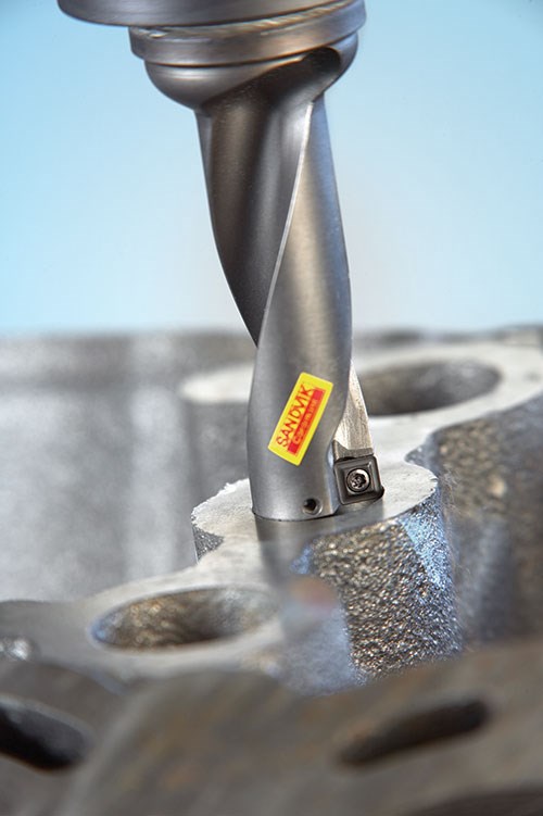
Sandvik Coromant offers 70 percent metric to 30 percent inch, and has seen an 8 to 10 percent increase in metric orders over the past 3 to 5 years, according to John Dotday, Product and Application Specialist.
As a global tooling company in the U.S. with counterparts in Europe and Asia, Sandvik Coromant needs to be highly flexible while continuously working on turn-key projects with their machine tool partners for which the machine/s will be shipped to another market. For many of these projects it is extremely important that they have a vast assortment of both metric and inch to support the customer’s requests, and also having the programming support from the machine tool builders to program the part dimensions in either inch or metric.
“Over the past 10 to 15 years we have seen a big change in the global marketplace with manufacturing companies looking to expand their operations in other markets. If we just take a quick look at the automotive industry, we see that five out of the top 10 American-made cars sold today in the U.S. are foreign models. The foreign auto manufacturers have built several large manufacturing facilities here in the U.S. bringing with them CNC mills and lathes already tooled and programmed to manufacture parts. Visiting these plants you will see extensive use of metric tools and CNC programs with metric dimensions.” Dotday believes that global expansions have dictated that cutting tool suppliers provide an extensive assortment of both metric and inch tools in their product offer.
6. Measurement
With the part finally produced, it needs to be measured and inspected. For most of the standard tools it makes sense to buy new metric micrometers, etc. Everyone is aware that tools with electronic displays can toggle between inch and metric. When it comes to inspection and measurement with gages it is a bit more complex.
George Schuetz, Director of Precision Gages at Mahr Federal notes that switching to metric for any company can be a daunting undertaking. “The world is demanding it from U.S. manufacturers, but there are many levels of switching over to make metric products and the one to choose depends on history, cost and the capability to speak multiple languages (inch and metric).”
Many core gage builders in the U.S. have been in business for a long time. The problem with these legacy companies is that over their history many of the gages are 20 to 50 years in the making. And for a large company there may be 10,000 gage designs that can still be made. Imagine the cost of going back and trying to convert the prints to begin manufacturing these parts in metric. It’s just not going to happen, according to Schuetz.
With that said, existing gages do not need to be replaced. New gages can be built to metric sizes if that is what is required.
Summary
Changing to metric should not be a big challenge, according to the arsenal of advice shared here. CAD and CAM can handle it—and even allow you to go back and forth from inch to metric while also telling the machine whether the program code is inch or metric. Many machining centers are typically more accurate when they are running in metric mode, and there is plenty of support for gages and measurement in metric. Most of the information we have presented here supports the metric change. As more American shop owners take a look and understand what is involved, they will make the change to metric.
Note: If you are making the transition to metric, keep in mind that this article represents just a sampling of the available resources. As with any change, the final responsibility is with the person making the change. Do your own research and make sure you understand all aspects of what is required. For each of the categories examined here there are numerous suppliers, well beyond the ones who were able to participate in this article. For those not included and interested in providing some comment, please contact the editor.
Related Content
Soft Wired: Cutting High Taper Angles with Wire EDM
Examine the wire’s properties to determine the right one for achieving the best cut.
Read MoreProject Reveals Added Benefits of New P20 Grade Steel in Machinability, Cycle Time and No Stress Relief
MoldMaking Technology's Christina Fuges talks with General Motors' Shane Appel about a project testing a new P20 steel grade's dimensional stability.
Read MoreLarge Hybrid Steel Insert Solves Deformation, Dimensionality, Cycle Time Problems
DMLS printers using metal additive powders selected by Linear AMS to produce high-quality, accurate, consistent 3D-printed mold components with certification and traceability.
Read MoreHow to Lower Cycle Times With the Right Tool Steel
Combining excellent mechanical properties, high wear resistance and high thermal conductivity in a specialty tool steel yields cycle time reduction.
Read MoreRead Next
Think Metric: It’s All in the Numbers, Part 2
Feedback from the field on making the metric conversion in your shop after realizing it just makes sense.
Read MoreAre You a Moldmaker Considering 3D Printing? Consider the 3D Printing Workshop at NPE2024
Presentations will cover 3D printing for mold tooling, material innovation, product development, bridge production and full-scale, high-volume additive manufacturing.
Read More
