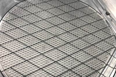
Figure 1. This laptop computer enclosure, featuring a keyboard web between the keys, was first seen in 2005. Due to the numerous knit lines in this design, it is crucial to provide ample vents to maximize weld line strength. In addition to vents, both primary and secondary vent relief channels must be sufficiently sized to allow gas to escape, ensuring a larger processing window and better part quality. Source (All images) | Michael Louris
It was a hot summer day in August 1987 at RKO Tool Corporation in Shoreview, Minnesota. I was finishing my first one-cavity mold after graduating from Hutchinson Vo-Tech College, where I received a degree in tool and die making, majoring in moldmaking. After 10 weeks of work, it was finally done, well, almost done. The only thing left was grinding the vents on the parting line.
Cutting vents is one of the most anxiety-inducing aspects of moldmaking because it’s the last step and if the vents are cut too deep and the part flashes, then the mold will come back like a boomerang. The customer is unhappy and so is the boss. If the vent is not deep enough, the full benefit of proper venting will never be realized, and the opportunity costs are forever unknown.
This is the elusive nature of mold ventilation.
Establishing Requirements
When I reconnected with Christina Fuges at MoldMaking Technology, 25 years after writing my last article, she asked me about the most important lesson I learned from managing tooling worldwide. My answer was venting. Venting is the most poorly designed, poorly understood and poorly executed aspect of tooling across all countries and industries.
In the late 1980s and early 1990s, I worked at Dynamic Engineering, one of the top mold shops in Minneapolis, where I learned how to build class 101 multi-cavity tooling. I then worked as an estimator and later as a tool procurement engineer at Thermotech, a well-respected United States molder providing close-tolerance parts to the automotive, defense, oil and gas and medical industries. The company molded glass-filled PPO, PET, PBT, PEI, PA66, PPS, POM and PEEK, for which the tooling and processing requirements are extraordinarily challenging.
For this reason, Thermotech had a mold specification manual to which the local high-precision tool shop contractors had to adhere when building molds for us. This increased tooling costs, but management knew that the ROI on the additional mold cost was longer mold life, better processing windows, higher part yields and, most importantly, improved customer satisfaction.
One section in the manual specifies the mold ventilation requirements. Not only did we require mold venting on parting lines, but we also required it on ejector pins, core pins, slides and lifters. The parting line vents were always perimeter vents, not whisker vents. Years of conversations with our seasoned processing engineers and tool designers laid the foundation for my appreciation of the importance of good mold ventilation.
At the time, we were fortunate to have a group of local precision mold builders who were experienced with the mold standards manual and would strictly follow it, ensuring that they met every aspect of our mold build requirements and built the tools to specification.
Because of the abundant venting on the parting line, the mold was much easier to fill and we were able to lower the packing pressure, which also reduced the residual stress in the part, decreasing part warpage. The team was shocked and delighted to see the results that were even better than I predicted.
Sticking to the Plan
In the spring of 2000, I started working for a consumer electronics and software company. One of my early projects was a laptop computer (see Figure 1). During the tool design review meeting, I clearly detailed how I wanted the perimeter vents to be cut and provided the reasons behind this approach. Since the vents were properly designed when we did the final tool design review, I expected they would be cut as we decided.
However, when I attended the tool trial and inspected the parts, the filling pressure was higher than expected, and there were cosmetic issues. There was also a cosmetically unacceptable weld line on the logo and gas marks in other areas. The part was high gloss, translucent PC, so the defects were highly visible.
When inspecting the parts, I noticed that the parting line was quite sharp and jagged when I rubbed my finger along the bottom edge of the top case part. I inspected the tool further and discovered they cut whisker vents instead of perimeter vents. I felt a flash of anger and disappointment. Then I paused and thought about that hot summer day in 1987 at RKO Tool, feeling nervous about cutting those vents.
I collected myself and asked them to accompany me to the conference room where we could discuss the importance of venting and why we need to machine the perimeter vents as originally specified as well as the need to add core insert vents.
After much negotiation, they reluctantly agreed, with one condition: a signed guarantee that if they followed my instructions and the mold flashed, the company would assume responsibility for the cost of the tool repair. I signed the document, and they proceeded to recut the vents per my request. We put the tool back in the press.
Once the tool was up to temperature, we started the molding process. The injection pressure was reduced by over 35%, the gate blush issue was resolved, and the bottom edge of the part was free of jagged flash and steps and had a smooth 0.05 mm radius.
Because of the abundant venting on the parting line, the mold was much easier to fill and we could lower the packing pressure, which also reduced the residual stress in the part, decreasing part warpage. The team was shocked and delighted to see the results that were even better than I predicted.

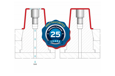
Figures 2 a, b and c Vent types demonstrate a variety of effective venting strategies. For example, (a) a laminate stack comprises multiple inserts assembled and inserted into a pocket formed by wire EDM. Each insert is fully vented, with primary relief channels enabling gas to escape along the sides of the core inserts. Secondary relief channels are machined on the support plate's surface, enabling gas to escape to the atmosphere between the A or B plate and the support plate. These channels are particularly useful for relieving gas traps at the center of a part. (b) The geometry on the face of the slide can be vented using this vent style. While many molds rely on natural venting around slides, it is preferable to design venting that allows gas to escape as easily and quickly as possible. This approach improves gas release, enlarges the processing window, and reduces maintenance costs associated with gas residue buildup in slide pockets. (c) Inserts, core pins, ejector pins, slides, and lifters should all be vented to facilitate quick and easy gas escape. This is especially important for high-volume, thin-wall, high-pressure/high-speed molded parts. Increased venting leads to a larger processing window, lower mold maintenance costs, reduced downtime, and better product quality. For materials with a V0 flame rating, maximum venting is essential due to the higher volume of gas produced as flame-retardant additives burn off during molding.
Continuing to Learn and Lead
Over the coming decades, I repeatedly encountered similar issues in shops worldwide. Despite emphasizing the importance of venting during mold design reviews and thoroughly checking final designs, I often found that tools did not meet the vent design specifications and were almost always cut too shallow. I spent many hours negotiating with tool shop managers, persuading them and their teams to cut vents as per the agreed-upon specifications (see Figure 2).
Hopefully, the lessons shared here motivate you to clearly communicate to ensure that all of your molds are vented correctly, benefiting everyone involved.
Related Content
Hands-on Workshop Teaches Mold Maintenance Process
Intensive workshop teaches the process of mold maintenance to help put an end to the firefighting culture of many toolrooms.
Read MoreRevisiting Some Hot Runner Fundamentals
What exactly does a hot runner do? If you’ve been in the injection molding industry for any length of time, you might think the answer is obvious, but it is not.
Read MoreHow to Correctly Size a Hydraulic Cylinder
This week Randy shares steps for correctly sizing a hydraulic cylinder on a mold.
Read MoreThe Ins and Outs of Hot Runner Temperature Control
A training checklist that explains the why and how of proper hot runner temperature control and system management.
Read MoreRead Next
Mold Design Review: The Complete Checklist
Gerardo (Jerry) Miranda III, former global tooling manager for Oakley sunglasses, reshares his complete mold design checklist, an essential part of the product time and cost-to-market process.
Read MoreA Different Approach to Mold Venting
Alternative venting valves can help overcome standard mold venting limitations and improve mold performance.
Read MoreHow to Improve Mold Venting with Metal Additive Manufacturing
Patented 3D-printed mold insert design rapidly evacuates gases while preventing plastic flash-through, eliminates costly maintenance and need for press-side temperature-control units.
Read More




.jpg;maxWidth=300;quality=90)


