Redefining CAM Technology for Moldmakers
Tool paths that dynamically adjust tool motion allow faster, safer machining without the need for high-speed equipment.
High-speed machining has been around for quite a while. Powerful controllers in combination with rigid machines and blinding-fast, high-speed spindles have long been able to remove material at astounding speeds on the straightaways. If you throw in some sharp curves or even corners where the tool can bury, however, you could wind up breaking several tools to machine a single part.
Getting the most out of high-speed machining using standard CAM tool paths previously required hours of programming to adjust feeds and speeds to appropriately compensate for material conditions ahead of the tool. The prudent CAM programmer would go to the machine to watch the first piece run, then slow down the feed rate and press the stop button if it looked like the tool was heading into trouble. Then he would go back to the CAM programming station and refine the high-speed tool paths even more.
This was time well-spent for production machining work, but for moldmaking, where the first piece is usually the last, it was often better to run the machine slowly, at the safest known feeds and speeds, and call it a day. So when you ask moldmakers if they want to learn about the latest advancements in high-speed machining, they often politely end the conversation. This is unfortunate, because CAM software has evolved to the point where substantial improvements in machine cycles and tool safety, as well as reduction in tool wear, can be achieved.
These improvements can be accomplished while the time required to create a CNC program also is reduced. Some still call these machining strategies “high-speed,” but new CAM technology is “high-speed-plus.” This means you can machine a lot faster and more safely on whatever CNC equipment you are using. Maybe it is time to call this CAM software technology something other than “high-speed” so that moldmakers who could sorely use its advantages will be encouraged to dip their feet in the water and see what it’s all about.
Toolpath Transition
Today, it is possible to create tool paths with advanced algorithms that analyze the material remaining to be machined ahead of the tool. The software automatically adjusts the feeds, speeds and tool motion to keep the tool in the best possible cutting position and better manage heat, preventing breakage and uneven tool wear. These algorithms will even base output on the type of tool being used and the material being cut to deliver the safest motion for those variables.
This capability can be referred to as dynamic motion rather than high-speed. In this context, we can define “dynamic” as constant modification of the cutter path based on the chip load/size the tool was designed to produce rather than based on just the part geometry. Dynamic adjustment of the tool motion, therefore, refers to the cutter continually striving to reach optimal cutting conditions based on the given conditions. And shops can realize benefits from dynamic motion on virtually any machine. High-speed equipment, of course, enables a shop to go gangbusters. However, even users of lower-spindle-speed, conventional equipment can benefit greatly from dynamic motion, because the actual motion generated by these machines still is always geared toward producing the optimal cut for those specific conditions.
Tool paths that dynamically adjust tool motion are simply more efficient, because they control the amount of material being removed based on the tool manufacturers’ specifications and use more of the tool’s cutting surface while adjusting for tool load, which can often trump raw speed on a non-dynamic cutter path. Since the tool paths are continually adjusting to obtain a target feed per tooth, they are remarkably consistent, making it possible to accurately predict tool wear.
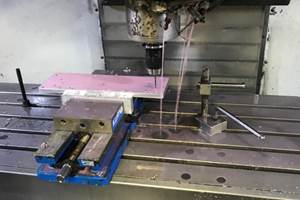
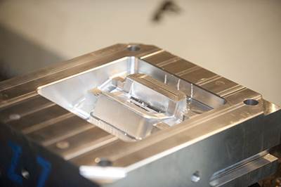
One such tool path was introduced several years ago, and one of the primary target applications was 2D pocketing, a frequent requirement in machining mold plates. Instead of light stepdowns and aggressive stepovers, this tool path uses a much smaller stepover that allows full-depth cuts. This means that rather than making two or three incremental cuts to machine an area, the tool can instead make one deeper, optimized cut. In many instances, this approach has delivered faster cycle times, ranging from 20- to even 75-percent faster. Additionally, tool life is dramatically increased, because the heat and wear can be managed and spread evenly. This not only saves tooling costs, but when you consider tool changes and labor, also brings down the total cost burden of a machine.
Today, this technology has been expanded to include not only the 2D machining that moldmakers make use of in mold plates, but complex 3D core and cavity roughing as well. It’s even been extended to machining applications such as turning.
Moldmakers who use dynamic motion technology can achieve improvements in programming time, cutting time and tool life, and these improvements can help users price their services more competitively while reducing lead times. In many instances, dynamic motion options are already available in software moldmakers currently own. They can simply select the dynamic motion equivalent of the tool path they are currently using and start from there. Within a few weeks of using these tool paths and incrementally adjusting feeds and speeds upward, they should clearly see the advantages.
Using tool paths that dynamically adjust tool motion, in conjunction with advanced cutting tools and adjustments based on radial chip thinning data and dry machining for steel, can enable moldmakers to achieve levels of CNC machining productivity that were previously thought to be impossible.
Related Content
Tips for Tackling Mold Design, Machining, Cutting Tool and Wear Challenges
Tips for tasks ranging from reducing risk in part design and taking advantage of five-axis machining to refining cutting tool performance and reducing wear with guiding and centering systems.
Read MoreHow a Small Programming Change Cuts Cycle Time in Half
Overriding the CAM system when milling a series of lifter pockets helps to improve metal removal rate and increase feed rates.
Read MoreFour Micro Tooling Considerations
Issues involving gating, ejection, mold splits and direction of pull are of special concern when it comes to micro tooling.
Read MoreHow to Fix Predicted Warpage Before It Happens with Windage and CAD Model Morphing
Applying windage and model-morphing techniques saved toolmaker/molder Sturgis Molded Products the time, cost, headaches of multiple part/mold design iteration loops, cumbersome cooling fixtures, and long molding cycles.
Read MoreRead Next
A Dynamic Approach to Prototype Tooling
Software that adapts to the demands of varying cutting conditions helps this moldmaker adapt to the demands of a varying workload.
Read MoreAre You a Moldmaker Considering 3D Printing? Consider the 3D Printing Workshop at NPE2024
Presentations will cover 3D printing for mold tooling, material innovation, product development, bridge production and full-scale, high-volume additive manufacturing.
Read MoreHow to Use Strategic Planning Tools, Data to Manage the Human Side of Business
Q&A with Marion Wells, MMT EAB member and founder of Human Asset Management.
Read More
