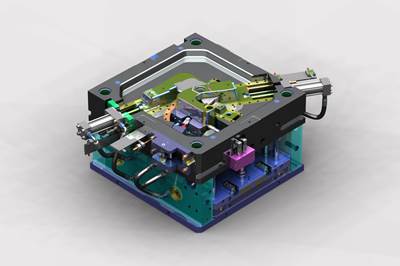
Moldmakers make changes to part and mold designs one to four times, which only stresses how vital it is to find ways to reduce risk in manufacturing. Photo Credit: Autodesk
Everyday mold builders face various challenges as they tackle each new mold project that enters the shop. Whether it involves engineering, building, maintaining, or repairing molds, this industry’s dedicated technology suppliers offer solutions. Here are some insights and instructions to help your team through four specific challenges.
1. How to Reduce Risk in Plastic Part Design and Manufacturing
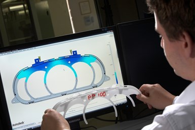
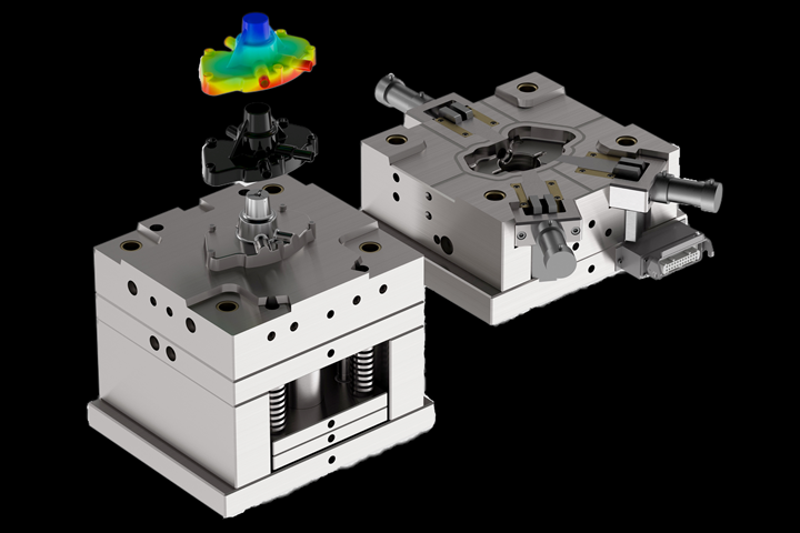
Upfront simulation workflows and design of experiments can be useful tools to reduce risk. Photo Credit: Autodesk
Dr. Matt Jaworski, a senior subject matter expert for Autodesk’s (Mill Valley, California) Moldflow Simulation Team, shares his insights on the value of mold flow simulation:
- The cost of change can be decreased with better decision-making early on.
- The design phase offers a unique area of time duringwhich we can impact the end product at a much lower cost.
- Common struggles of putting simulation in the hands of designers include:
- Making changes and shifting established processes and workflows is difficult
- Upper-level buy-in is required
- Experience is required
- A lack of time and details does not match the required accuracy and time
- Outsourcing this part of the process can create extra iteration costs.
- The power of the design of experiments lies in the ability to see the sensitivity of user-defined variables and quality criteria, as well as the use of this information later in the process.
- With simulation, you can evaluate part design decisions, optimize manufacturability, eliminate potential molding issues and solve part tolerance issues.
- Simulation expands overall team knowledge of how plastics and molds work for designers, mold builders and plastics engineers.
- Linking simulation with the injection molding machine eliminates simulation data waste.
- Seek knowledgeable experience and a guided implementation plan.
How to Take Advantage of 3+2 and Simultaneous 5-Axis Machining to Increase Productivity
“First, think about what you are doing and why,” emphasizes Ken Conklin, the director of the Methods Dealer Network for Methods Machine Tools (Charlotte, North Carolina), as he shares his advice on how to implement 5-axis machining in mold manufacturing.
- Five-axis machining is great for complex shapes (more tools to do more things), reduces cycle times, decreases setup time (you are getting five sides; no flipping or flopping; you get better relational accuracy versus dimensional accuracy), allows better tool usage (using tools not previously used), lessens the chance of human error and reduces the need for expensive or special fixtures. Your part is only going to be as good as your CNC strategy and CNC tool.
- Use 5-axis simulation tool paths to your advantage.
- The most common machine type is trunnion because it is more rigid, better for hard milling and is a solid bridge-style machine for mold and die.
- Kinematics is important. Know where your kinematic center is and verify that its rotation is true, including the tilt, rotation and finding the pivot point.
- Maintaining surface footage is critical.
- Don’t think about using a 5-axis machine without the right programming.
- Tool center point control allows you to program a feed rate of 200 inches per minute (ipm), and the control will make adjustments on the fly.
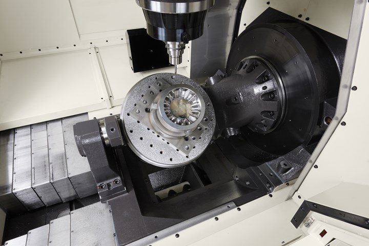
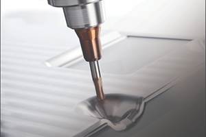
A highly accurate, rigid, and reliable solution for 5-axis mold and die machining can deliver high performance for high-precision machining of extremely hard materials in complicated shapes which are difficult for a 3-axis machine. Photo Credit: Methods Machine Tools
- Zero is not your friend when it comes to your tools. In 5-axis machining, a 0 is a problem and causes singularity issues. Some CAM software can help—otherwise, you must remove it from your programming.
- CAM can make you or break you when it comes to 5-axis machining.
- CAM verifies your tool paths, not your machine motion. Verification software is vital when it comes to simultaneous 5-axis machining.
- Adaptive milling—a good 5-axis programmer can eliminate some additional semi-roughing passes because he can get into places he couldn’t before.
- The machine tool matters—make sure tilt and rotary are as accurate as possible.
- Stabilization of the machine in a shop environment is critical to maintaining accuracy.
How to Define Cutting Tool Performance
The dirty little secret about cutting tool cost is that it’s not about price: it’s about overall costs. Stas Mylek, Partnership Program Manager for CNC Software (developers of Mastercam, Tolland, Connecticut), offers some advice:
- There are three cutting tool cost myths: Use tool price as a gauge, cutting inventory cost improves job profitability and you don’t need to involve a CNC programmer in the purchase.
- Look at where performance truly lies with your cutting tools and measure data.
- Use cutting tool supplier cutting parameters and speeds and feeds recommendations. They know their tools best.
- Price versus cost: Cost requires measurement with benchmark testing.
- It’s a constant balancing act between performance and tool life and/or tool life and material removal rate.
- A lot of published cutting tool data is conservative and meant to be a starting point. It does not give you a good indication of where you can push it.
- Strategies like Dynamic Motion help you squeeze out more from a cutting tool.
- Contemporary toolpath strategies are vital.
- More expensive cutters tend to have higher quality carbide and better coatings, which aid with performance.
- If all you do is look at inventory costs, you still need to measure cutter performance first!
- Keep up with cutter innovations—geometries, coatings, tool path strategies. Homework will page huge dividends.
- You must drive cutting tools properly to maintain a consistent chip load to gain tool life.
- Higher-priced tools tend to be on top for several reasons: engineering, quality carbide, coatings, design, quality—much of what you expect out of a top tool.
- The calculator has been expanded to include insert or high feed cutters and to factor in things like regrinds.
- Although there are inherent benefits to more modern machines, shops can see a dramatic improvement in almost any milling machine/tool combination.
How to Achieve Flexibility and Reduced Wear with Guiding and Centering Systems
Agathon’s (Bethel, Connecticut) Christoph Meier, engineering manager – Special Projects Applications shares how to select the next guiding system, fine centering system, or ejector guiding components for your injection molds.
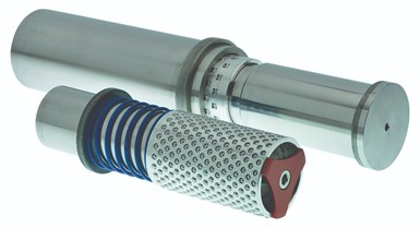
Alternative guiding systems can address common mold builder challenges. Photo Credit: Agathon
- Know the difference between sliding and rolling guides.
- Understand the advantages and disadvantages of friction guides and anti-friction guides/rolling elements.
- True cost considerations must include wear and reduced maintenance.
- Alternative guiding systems can address shrinking profit margins (due to expensive maintenance and too many part rejects); planning reliability (time pressure, spare parts availability); higher productivity (parts per shot, speed); and upgrades that are hard to realize due to rework, etc.
- A new guiding system with a rolling bushing system offers one system that guides and centers the parting line without backlash.
- Key features to look for include profile rollers; free space to add more mold inserts to increase productivity; flexible collar retaining ring, which can be positioned individually, with one item used for several plate thicknesses; long centering stroke and a flexible collar concept that means only one system required in stock for higher operational reliability.
- A fine centering system is a cost-efficient alternative to a side lock, flat-centered device, or tapered/conical centering system.
- Offers flexibility, as the mold builder is not beholden to using four. You can use two, three, four, five, or however many you need. It also uses a spring mechanism, hardened pillar, bushing, chamfered inlet geometry and a fully equipped roller cage.
To access free webinars on these four topics, click here.
Related Content
Revisiting Some Hot Runner Fundamentals
What exactly does a hot runner do? If you’ve been in the injection molding industry for any length of time, you might think the answer is obvious, but it is not.
Read MoreTreatment and Disposal of Used Metalworking Fluids
With greater emphasis on fluid longevity and fluid recycling, it is important to remember that water-based metalworking fluids are “consumable” and have a finite life.
Read MoreLaser Welding Versus Micro Welding
The latest battle in finely detailed restoration/repair of mold materials.
Read MoreMoldmakers Deserve a Total Production Solution
Stability, spindle speed and software are essential consideration for your moldmaking machine tool.
Read MoreRead Next
Five Ways to Tackle Tough Mold Design Tasks with Digitalization
Transform static 3D designs into animated 4D designs that simulate motion and interaction of complete mold systems to improve design workflow.
Read MoreCutting Tool Considerations as Mold Complexity Increases
A look from the shop floor at some of the factors to consider during your cutting tool selection decision-making process to optimize your mold machining operations.
Read MoreHow to Use Strategic Planning Tools, Data to Manage the Human Side of Business
Q&A with Marion Wells, MMT EAB member and founder of Human Asset Management.
Read More


