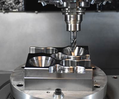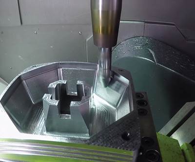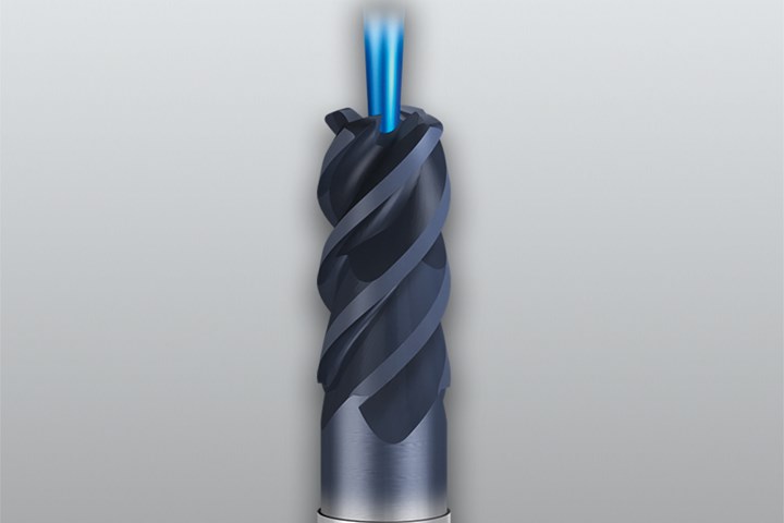
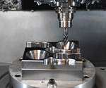
Duplex end mills make it possible to do pocket milling and slot milling (2D) as well as complex 3D operations such as copy or high-feed milling with one tool. Photo Credit: Emuge-Franken N.A.
If there’s one thing for certain in manufacturing, it’s that shops should always be open to new ideas. Moldmakers have found this to be especially true with high-efficiency and trochoidal toolpaths, often enjoying significant productivity and tool life improvements after adopting these metal removal strategies.
Similar productivity success stories in moldmaking are happening by applying new technology through the use of circle segment tools (conical barrel cutters). For shops with five-axis machining centers, this milling approach can yield time reductions of 90% or more and result in better surface finishes.
What was once a 38-minute cycle time per pocket fell to just over 19 minutes, nearly a 50% improvement, all with just a small programming change.
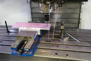
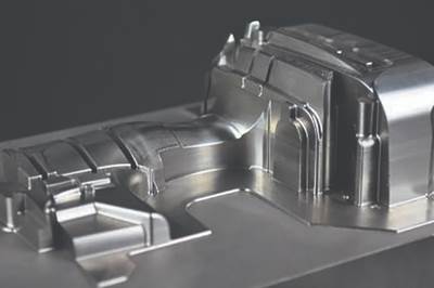
And while each of these milling technologies has its merits, it’s important to remember that there’s more than one way to skin the proverbial cat. This was the case recently with a North American plastic injection moldmaker, who wanted to optimize its milling process for machining a series of lifter pockets in P20 tool steel. The job involved squarish, relatively deep cavities with tapered sidewalls, used to house a sliding mechanism for the ejection of the molded workpiece. It is a common feature on many of their mold cavities, but had long been a thorn in their side due to its machining challenges.
The finishing application was ideal for circle segment end mills. However, the customer’s CAM system did not support these tools. What it did support was the traditional approach—helical ramping into the workpiece 1.5 tool diameters deep, trochoidal milling outwards to complete that section of the pocket, and then milling the tapered walls by moving the cutter upwards and outwards until reaching the starting plane.
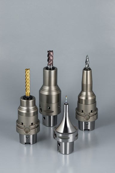
High-precision and high-performance mill/drill chucks provide rigidity, vibration dampening, concentricity, machining speed and tool life versus conventional chuck technologies for milling and drilling applications.
This process was repeated until reaching the pocket’s full depth. A four-flute duplex end mill and FPC milling chuck were used, but not to their fullest potential.
Since the walls were tapered, material removal was not consistent because with each successive pass around the pocket’s periphery, the axial depth of cut and radial depth of cut decreased. The roughing cycle did not offer a way to increase feed rates as the tool rose higher in the pocket to compensate for effective chip thickness.
Using an insertable style end mill with high-feed face geometry was considered for taking shallow depths of cut throughout the entire pocket feature. However, that may work for large pockets but may not be suitable for the small pockets.
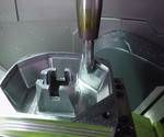
It was time to re-think the machining process. Following application advice, the moldmaker decided to go with an unconventional approach, overriding the roughing tool path strategy from its CAM system while using the current end mill and tool holder. Rather than milling the tapered sidewalls immediately after roughing each depth section, they saved that task for the end—once the pocket was completely roughed out, they retracted to the top of the workpiece, then drove the cutter around the interior in a Z-negative direction.
The end mill’s dual features made the metal removal rate fairly consistent throughout the machining process. For example, the tool features the traditional characteristics of an end mill, combined with the high-feed cutting face of an insertable tool. The shop also could drastically increase feed rates—instead of the 40 ipm used throughout the previous roughing strategy, the programmer was able to boost to 300 ipm during the tapered wall machining.What was once a 38-minute cycle time per pocket fell to just over 19 minutes, nearly a 50% improvement, all with just a small programming change. This is an excellent example of what’s possible when thinking outside the box.
Related Content
What is Scientific Maintenance? Part 2
Part two of this three-part series explains specific data that toolrooms must collect, analyze and use to truly advance to a scientific maintenance culture where you can measure real data and drive decisions.
Read MoreHow to Analyze and Optimize Cutting Conditions to Reduce Cycle Time
Plastic injection mold design and manufacturing company puts NC program optimization software module to the test. The results were surprising.
Read MoreHow to Manage Wall Thickness Changes in Your Mold Design
To ensure even filling and cooling, consider wall section transitions, corners and fillets, ribs and bosses, lip and rim designs and CAE flow simulation software.
Read MoreHow to Fix Predicted Warpage Before It Happens with Windage and CAD Model Morphing
Applying windage and model-morphing techniques saved toolmaker/molder Sturgis Molded Products the time, cost, headaches of multiple part/mold design iteration loops, cumbersome cooling fixtures, and long molding cycles.
Read MoreRead Next
Cutter Considerations for Hybrid Additive Manufacturing
Four tips for applying the right cutting tools in hybrid additive manufacturing.
Read MoreA Strategy for Better Mold Finishes
Combining advanced tool geometry and complementary CAM tool paths can reduce finish cycle times and improve surface quality.
Read MoreRunning Circles Around Milling Challenges
Circle-segment end mills can greatly improve five-axis mold prefinishing and finishing operations.
Read More.png;maxWidth=970;quality=90)



.png;maxWidth=300;quality=90)


