Plastic Injection Molding Starts with the Pellet
This is the first article in a new series that will examine the injection molding process by breaking down the path a plastic pellet takes as it is transformed from Pellet 2 Part. It covers what every moldmaker should know about raw materials, including the fundamentals of viscosity curves, Melt Flow Index, Melt Flow Rate, shear and more.

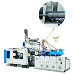
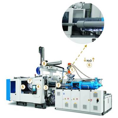
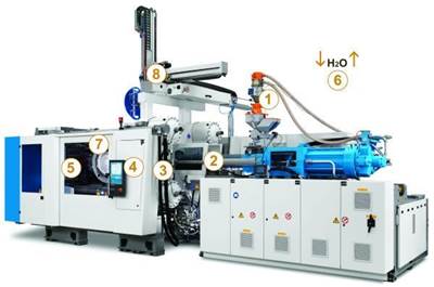
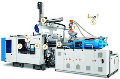
This article series will review (1) raw material; (2) the melt delivery system: screw, valve and end cap; (3) hot and cold runner systems; (4) hot runner controllers; (5) mold cooling optimized by design; (6) plant water system impact on performance; (7) new and innovative mold cooling technologies; and (8) automated part handling. Image courtesy of KraussMaffei.
To begin this 11-part series on plastic injection molding, I propose that you keep an open mind and consider modernizing your current approach to mold manufacturing, making the effort to understand other areas of our industry in
greater, practical detail.
Challenge yourself to ask “Why?” before dismissing something new. As the year and series progress, we will reveal the steps of the injection molding process, beginning with the plastic pellet and through its transformation into a part. The series will also review the basics of energy management, including its generation, application, control and removal within the process.
We want you, the reader, to learn from the daily processing challenges we present and then be able to provide permanent solutions for your customers. This approach has the potential to transform your business.
The Raw Material
The selection of raw material will set the direction for the design of the mold. Each plastic injection mold build should start with a design for manufacturing (DFM) meeting that includes the mold builder, injection molder, raw material (polymer/resin) provider, flow simulation provider and hot runner manifold supplier (if applicable). Although more questions undoubtedly will arise, the discussion should at least include answers to the following questions:
1. What is the specific grade of raw material?
2. How does that material flow?
3. Are there fillers or additives?
4. What are the estimated shrinkage values?
5. What are the injection molder’s standards?
6. What temperature will the mold run at?
7. What are the part dimension and performance requirements?
8. What is the required cycle time?
Flow simulation, commonly known as “mold flow” in our industry (also the trademarked name of a software program), can provide critical information to the part designer, mold builder and injection molder concerning knit line locations, press size, cycle time and other important mold-build details. If a polymer flow simulation is provided, the report will already have taken into account the viscosity curve data (see Graph) used by the simulation provider. If it is not provided, research on the polymer to be used will be required. It is important that only exact data for the specific raw material is used. Substitutions can diminish the accuracy and value of any simulation. Generalizations and assumptions can translate into larger molding machines, longer cycle times, tool rework, part defects, scrap and even part failure.
The mold builder’s engineering decisions related to the delivery system, gating, cooling and venting will have direct impact on the raw material’s performance in the molding process. This performance can ultimately impact many part properties, including surface quality, knit line strength, part ejection force (sticking), dimensions, tolerances, total cycle time and overall mechanical properties.
Terminology
Injection molders expect mold builders to be experts in the raw materials used in their molds and to have relationships with material suppliers. This expertise leads to molds optimized for high-volume production with large processing windows, which results in on-time delivery of high-quality parts that meet project requirements at lower cost. In order to meet this demand to be well-informed about the raw materials, it is important for moldmakers to understand and apply the following terms in their day-to-day mold-design and building processes:
Shear is the change in viscosity brought on by one layer of polymer sliding against another layer of polymer. Shear occurs in multiple locations within the molding process, including:
1. Injection mold machine screw, barrel and nozzle.
2. Sprue bushing, cold or hot runner system.
3. Gate point on the part (typically, the highest shear is at the gate).
4. Part geometry of the cavity.
Some poor injection molding results such as splay, gate blush, halo, degraded material, and brown or color streaking are tied directly to uncontrolled shear. Only area number 1 is controlled by the molder; the other three areas are the mold builder’s responsibility.
Knowing and understanding flow, shear, viscosity and the polymer limits can help determine hot runner drop location, gate type, gate sizing, venting and vent placement, etc.
Viscosity and viscosity curves refer to a polymer’s “molten thickness” or resistance to flow. High viscosity means less fluidity (flows like concrete), while low viscosity equals more fluidity (flows like water). Understanding this gives the mold builder a point of reference for best practices in mold design and the relative tolerances needed to manufacture the mold for the specific applications and raw materials. For example, too much clearance in the components or vents for a low-viscosity (high-flow) polymer could lead to flash.
Melt Flow Index (MFI) and Melt Flow Rate (MFR) are two specific tests used to determine the ease of flow for the given polymer at very low shear rates. These tests were developed to check the flow behavior consistency of a polymer from one sample to another, but they can be misleading if used to compare flow characteristics of two different polymers at the high shear rates normally achieved in injection molding.
Next Step
The goal of this background on raw material properties is to provide insight on how they interact with one another and, ultimately, how they influence the molded product. Understanding and applying this knowledge is the next step in designing and building molds for performance and reliability. In this way, a mold builder can eliminate potential problems before they get to the injection molder, becoming a more valued partner in the complex injection molding process.
The mold is one part of the entire injection molding process that needs to interact seamlessly with the other components. It can’t limit the process window or impact production uptime in a negative way. It also must meet market demand on price point, tool quality and lead time. Simple, right?
The mold’s value should be measured by its direct influence on the total net profit of the molded piece part, sustained over the life of the mold or the length of the part program. This thinking requires a cultural shift within the plastics industry. So are you up for the challenge of change?
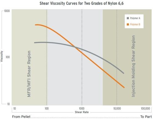
Graph courtesy of Ascend Performance Materials.
Related Content
Revisiting Some Hot Runner Fundamentals
What exactly does a hot runner do? If you’ve been in the injection molding industry for any length of time, you might think the answer is obvious, but it is not.
Read MoreMachining Center Spindles: What You Need to Know
Why and how to research spindle technology before purchasing a machining center.
Read MoreHow to Eliminate Chatter
Here are techniques commonly used to combat chatter and guidelines to establish a foundation for optimizing the moldmaking process.
Read MoreHow to Correctly Size a Hydraulic Cylinder
This week Randy shares steps for correctly sizing a hydraulic cylinder on a mold.
Read MoreRead Next
Initial Pellet Contact is the Screw
Here’s what every moldmaker should know about an injection molding machine’s reciprocating screw, which is often misunderstood and applied to the process incorrectly.
Read MoreDesigning a Better Heat Exchanger - Part 1
In a three-part sub-series, we review considerations for mold water cooling systems.
Read MoreControlling the Melt Delivery System Heat Source
Understanding the heating systems along the melt delivery path is critical to setting up a robust process and properly diagnosing problems.
Read More
