Designing 48 Individual Cavities in One Mold Plate
In the innovatively designed multi-cavity mold described here, every cavity has its own plunger injection system, ensuring that each cavity is filled completely and accurately with the desired amount of melt.
This project involved encapsulating an electronic subassembly for a sensor with a protective housing using injection molding. The moldmaker and raw material manufacturer worked closely together to select a material for the housing that satisfied the user's specifications and also was suitable for encapsulation. The choice fell to the liquid crystalline polymer - LCP Vectra E 130i, manufactured by Ticona GmbH (Frankfurt, Germany). The main reasons for this decision were:
- The good flow properties of the LCP melt.1 This is necessary to ensure that the coil, which is wound onto a ferrite core (outside diameter 4.5 mm, height 3.0 mm, wire diameter 0.3 mm), is not damaged during the injection molding process.
- The possibility of producing wall thickness of less than 0.2 mm.
- The excellent heat resistance of 275'C (HDT/A at 1.8 MPa) of the selected LCP grade.1 This is necessary because the subassembly is to be soldered onto a printed circuit board in an infrared oven as a surface mounted device (SMD).
- The very smooth, pore-free surface attainable with LCP for the housing, which, despite its very small surface area, allows the use of suction grips for automated assembly.
The outsert technique has proven particularly successful for the series production of electrical components.} Furthermore, it is usual - as in the manufacture of plug connector strips for example - to unwind a pre-punched metal strip from a roll, pass it through the injection molding machine, encapsulate it section by section, and then, after leaving the machine, further process it straight away or rewind it. The metal strip is not cut until subsequent processing, saving time-consuming operations for separating and positioning the moldings.
Outsert Technique With Prefabricated Metal Strip
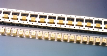
In a similar way, it was necessary with this prefabricated subassembly to pass it through the injection molding machine while still on the metal strip, and to encapsulate it using the outsert technique. Figure 1 shows prefabricated electronic subassemblies on a metal strip after they were encapsulated with LCP. The components are wrapped in film for protection during transport.
For economical series production, a multi-cavity mold was needed that could accommodate two rows, each with 24 subassemblies. With a conventional hot runner mold, a runner with a complicated balance would have been required, which - in relation to the low volume of the components - would have resulted in much too large a melt content and consequently in a long dwell time. Apart from this, it is extremely difficult, even with a naturally balanced hot runner, to feed the small quantity of melt evenly into the cavities. Even minor temperature fluctuations lead to irregular filling.
All of these problems have been solved by an innovative injection mold. Its functioning principle has since been patented.3 For this mold, a hot runner-like melt flow-way system was designed and built, which essentially consists of standardized components. This system, as will be explained in detail later, assumes the task of transporting the melt from the plasticising unit to the antechamber - which is in the form of a hollow cylinder - on each of the type 4NLS needle valve nozzles.
Plunger Injection System for Each Cavity
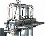
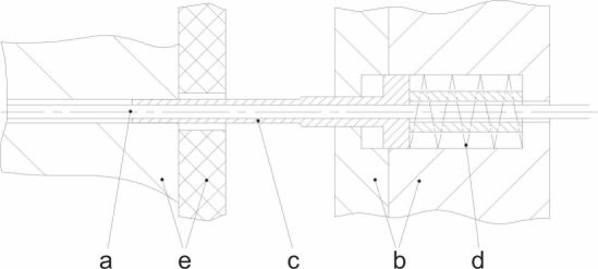
Unlike in a conventional hot runner system, a local plunger injection system is positioned at the back end of every needle valve (see Figure 2). It consists of a tubular plunger, which acts on the hollow cylinder (antechamber) between the 2 mm thick needle and the 3.5 mm diameter runner. As a result, the feeding of the melt with the aid of the plasticizing unit is entirely separate from the injection into each of the cavities. This process also is known as transfer injection molding.
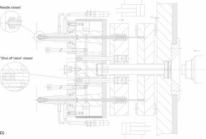
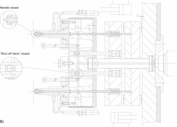
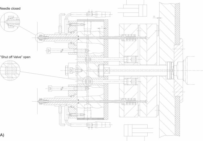
A cross-section through the mold shows the four main functional groups (see Figure 3):
- A long gate bushing, heated from the mains, guides the melt from plasticising unit to a hot runner plate.
- The hot runner plate, heated to the temperature of the melt by 230 V heaters made of cast brass, has two rows, each with 24 needle valve nozzles. For closely positioned cavities down to 12 mm apart, and for uniform temperature control, the nozzles are equipped with 24 V heaters. The antechamber between the tubular plunger and the runner is filled with melt via simple runners (see Figure 2). A central valve for each of the two rows can release or block off the melt flow.
- Mold plate assembly No. 1 holds the needle valves, and can open and shut them by moving 1.5 mm.
- Mold plate assembly No. 2 activates - one after the other - first the two valves and then the tubular plunger on each needle valve. With a stroke of 10 mm, each of these tubular plungers injects the melt waiting in the antechamber into the respective cavity.
To be precise, this mold is not really a 48-cavity mold in the conventional sense, but a mold in which 48 individual cavities have been accommodated in a joint mold plate. This makes it possible to dispense with the complicated balance for a hot runner system and to sequentially convey the melt via simple runners to the needle valve nozzles.
This mold concept offers the following advantages in injection molding:
- The melt flow-way system has very low melt content.
- The cavities can be positioned very close to each other. In the mold described here, the distance between them is only 12 mm.
- Injection with the tubular plunger ensures that each cavity is completely full and not overfed, even if temperature fluctuations should occur in the runner plate.
- The mold offers a very high level of operating reliability and availability.
The functioning procedure for an injection molding cycle is shown in the four parts of Figure 3. During the first step (see Figure 3A), the needles of the needle valve nozzles keep the gates closed. The injection stroke of the screw forces the melt out of the screw antechamber via the gate bushing, the two valves and the runners into the antechambers around the valve needles. As a result, the right amount of melt for the injection is ready in each plunger injection unit.
In the second step (see Figure 3B), plate pair No. 2 moves in the direction of the runner. With this, the valves close the connection to the plasticizing unit. The plastic melt now enclosed in the runner system no longer can flow back to the machine nozzle. Through the movement of the plates and the spring assembly behind the tubular plunger, a melt pressure of 600 to 800 bar is built up.
In the next step (see Figure 3C), mold plate assembly No. 1 travels with the needle valves in the direction of the plate, thereby opening the gate to the component. At the same time, plate assembly No. 2 continues its movement so that the tubular plunger can inject the melt located in the hollow cylinder into the cavity. The injection pressure is around 2,500 bar.
After the holding pressure time and cooling time have elapsed, both of the plate assemblies return in the final fourth step (see Figure 3D) to their original position. The needle valves close off the gate. The valves clear the way for the melt that has since plasticised, so that a new cycle can begin with the feed stroke of the screw.
Control of these processes is the job of the core puller and injection control systems of the injection molding machine, but their functions are swapped over. The core puller control system monitors the screw advance for filling the plunger injection molding units. The movement of both pairs of plates is regulated by the injection control system. The injection pressure and injection speed can, as usual, be adjusted - in steps, if necessary - via the volume flow and pressure of the hydraulic oil.
The design of the mold takes into account the requirements for optimum processing of LCP.4 Through the slow opening and the conical fit of the needle valve, the desired high shear of the LCP melt in the gate occurs as soon as the injection begins. As a result, its viscosity falls heavily so that even fine structures and thin-wall areas are filled perfectly.
System Passes Its Test
The mold concept has been used in series production for a year. It works with a cycle time of less than 15 seconds and has encapsulated some 50 million components with more than one million shots.
There have been no significant malfunctions during this time, and above all, the uniform filling behavior for each of the cavities has been confirmed. Due to the special flow properties of the LCP melt4, the strain on the component, especially on the coil wire that is only 0.3 mm thick, remains so low during the injection process that the reject rate is well below 0.5 percent - a figure that the customer describes as extremely good and previously unattained. This innovative mold concept can be applied universally wherever a large number of small cavities have to be filled evenly with a small quantity of melt and a conventional hot runner cannot be used for reasons of space or dwell time.
REFERENCES
1Vectra - Fulssigkristallines Polymer (LCP). Firmenschrift, Ticona GmbH, Frankfurt am Main 1997.
}Outsert-Technik mit Hostaform. Broschure C.3.5 der Reihe "Berechnen, Gestalten, Anwenden." Firmenschrift Ticona GmbH, Frankfurt am Main 1991.
3DE-PS 196 32 315 C 1: Verfahren und Vorrichtung zur gleichzeitigen Herstellung von Kleinstspritzguteilen aus thermoplastischen oder vernetzenden Polymeren (1996). G"rlich, R.
4G"rlich, R.; Gunther, H.; Scholtz, J.: Flussigkristalline Polymere spritzgieβen. Plastverarbeiter 47 (1996) 5, S. 92-94.
![]()
Related Content
Tips for Tackling Mold Design, Machining, Cutting Tool and Wear Challenges
Tips for tasks ranging from reducing risk in part design and taking advantage of five-axis machining to refining cutting tool performance and reducing wear with guiding and centering systems.
Read MoreHow to Select a Mold Temperature Controller
White paper shares how cooling channel analysis, which collects maximum pressure drop, total flow rate and heat dissipation, eases the performance evaluation of mold temperature controllers.
Read MoreWhat Is Scientific Maintenance? Part 1
How to create a scientific maintenance plan based on a toolroom’s current data collection and usage.
Read MoreFour Micro Tooling Considerations
Issues involving gating, ejection, mold splits and direction of pull are of special concern when it comes to micro tooling.
Read MoreRead Next
Advances in Hot Runner Systems Drive Innovations in Part Engineering and Styling
Design and performance capabilities of components fabricated in state-of-the-art molds enhance the appeal of new vehicles.
Read MoreAre You a Moldmaker Considering 3D Printing? Consider the 3D Printing Workshop at NPE2024
Presentations will cover 3D printing for mold tooling, material innovation, product development, bridge production and full-scale, high-volume additive manufacturing.
Read MoreHow to Use Continuing Education to Remain Competitive in Moldmaking
Continued training helps moldmakers make tooling decisions and properly use the latest cutting tool to efficiently machine high-quality molds.
Read More
