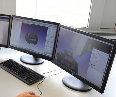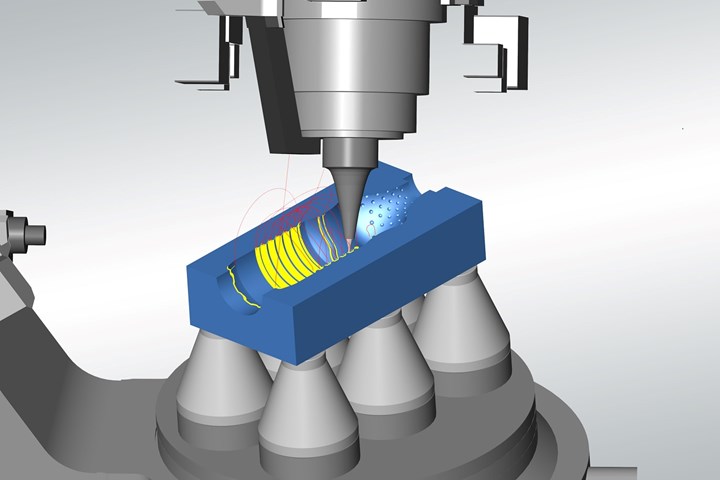
Virtual machining in CAM software offers powerful NC code optimization and simulation. Photo Credit, all images: Open Mind Technologies AG
Blow molds are used to produce many items that we use every day, such as drinking bottles (food and beverage industry), perfume bottles (cosmetic industry), bottles and containers for medicines (pharmaceutical industry), or bottles and containers for creams or other care products (household and care industries). The various materials used for the final products require different techniques to bring the material into the final shape.
For example, two methods are typically used to produce a plastic drink bottle. Depending on the quality and quantity of the final product required, it will either be produced using extrusion blow molding or injection stretch blow molding. The difference between the two processes is that injection stretch blow molding uses a preform that already has its final form around the neck of the bottle, including the thread from a previous process. On the other hand, extrusion blow molding extrudes a tube that will then be inflated into the mold to shape the product.
Blow Mold Design and Quality Considerations
Quality requirements for the molds are demanding for all types of bottles and containers due to their various geometries and details. In addition, due to more complicated bottle designs, molds are also becoming increasingly complex. Added features can include functional items such as grips, decorative features and individual brand logos.
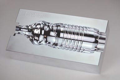
Bottle mold performance is largely determined by aesthetics, making machining and CAM software critical.
Additionally, the molds usually require a polished surface finish for production, often performed by semi-automated processes or done manually. Visual results largely determine the “performance” of a bottle mold, so the machining process is paramount. Plus, a workflow that minimizes the requirement for manual processes has a significant impact on mold production. To precisely meet these requirements, innovative CAM software is mandatory.
Traditionally, bottle shapes had simpler designs, and it was sufficient for molds to be produced on three-axis machines. This process dramatically lowers the capital investment by the mold producers but has many drawbacks. Not only are the geometric shapes restricted due to the access limitations of a three-axis milling machine, but three other manufacturing issues also impact results:
- A three-axis machining process for bottle mold shapes will typically require longer cutting tools, which also have lower performance than five-axis machines with short cutting tools. For example, for a cantilevered element such as a cutter stick-out from a holder, a 10% increase in cutter length will have an increased deflection of 30%, resulting in longer machining times and lower surface finish on the mold itself.
- The advanced geometry on modern molds also often has geometry with undercuts. Undercut regions have geometry that does not offer a direct line of sight with a fixed view as needed when three-axis machining. These regions then require three-axis machining with special types of cutters or additional time-consuming setups on the machine.
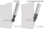
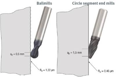
- Using the three-axis machining process across the semi-circular profile of a bottle mold will result in a varying contact point along the cutter. As the cutter’s contact point and effective radius change, the proper cutting technology should be changed. Otherwise, the result is a degradation of the surface finish.
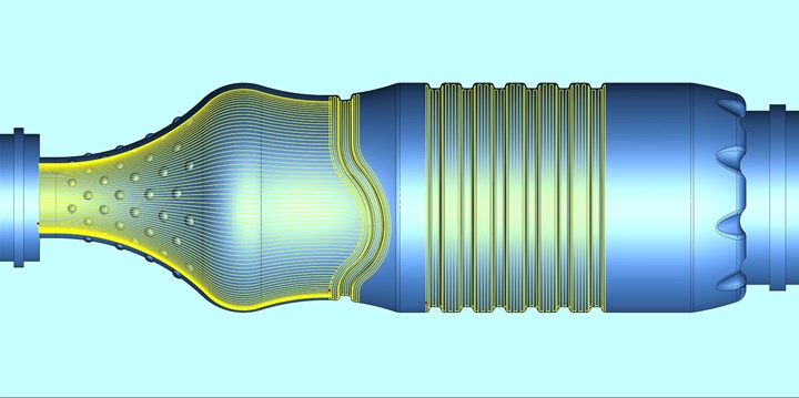
Customized CAM software has innovative strategies for generating toolpaths to produce high-quality surface finishes.
Blow Molds Meet Customized CAM for Five-Axis Machining
Mold production using five-axis machines addresses these points. Having the added flexibility of tool orientation enables the inclusion of complex model features for functional, aesthetic or marketing purposes. Five-axis machining is well understood to use shorter cutters, leading to increased cutter rigidity and faster machining. In addition, the cutting tool orientation can be used to control the contact point on the cutter, which improves the surface finish.
Also, an added “tilt” axis can be used to avoid contact along the tip or centerline of the cutter, where there is zero effective radius and poor cutting conditions. An added tilt angle of the cutting tool will reduce the impact of the “pole” situation where the cutting tool orientation is near-axial and results in large C-axis movements of the milling machine.
By considering bottle molds as a class of parts that typically has a circular shape, a simple user interface will streamline the programmer’s selections in the CAM software.
Depending on the arrangement of machine axes, the result can go beyond the axis stroke limits in other machine configurations, and depending on the machine controller, the large motions can lead to a dwell mark or lower surface finish. If the goal is to obtain a finishing quality from the machine, which competes with hand polishing, this can already be a critical point determining success or failure.
The toolpath calculation for bottle molds differs from standard machining cycles. By considering bottle molds as a class of parts that typically has a circular shape, a simple user interface will streamline the programmer’s selections in the CAM software. Ideally, the machining process will produce the surface finish quality that mitigates or eliminates the need for manual post-machining finishing processes.

To achieve a higher surface finish it is important to use dedicated machining cycles with high technology capability.
Dedicated machining cycles with high technology capability can help achieve a higher surface finish. For example, one technique is to calculate the toolpaths directly and precisely on the model surface instead of on an approximated mesh commonly used in CAM software. Another is a smooth overlap technique that greatly improves blending areas on the mold between and at the boundaries of a toolpath and a model feature.
To avoid problems during the molding process, all machining steps need to produce sharp corners at the joining of top and bottom mold halves. An automated tangent extension function is required in the model preparation to avoid the manual CAD steps to extend the multiple surface entities of today’s complex designs. Without the tangent extensions, the typical toolpath will roll over the sharp corners, making small rounds and impacting the performance of the molding process.
Together with a strong simulation and optimization of the entire machining process, these considerations define a robust process to produce the blow molds efficiently and achieve the required quality.
Related Content
Innovative Mold Building Enhances Packaging Material Efficiency, Elevates Recyclable Design
A manufacturing-focused design and optimized tooling enhance material efficiency in packaging for a new medical instrument.
Read MoreHammonton Mold, ADOP France Forge Strategic Partnership in Injection Blow Moldmaking
Hammonton Mold Inc., a leading full-service mold shop based in New Jersey specializing in injection blow molds (IBM), proudly announces its official partnership with ADOP France, a prominent IBM mold manufacturer based in Normandy, France.
Read MoreWhat is Driving Mold Lifecycle Management Digitalization?
OEMs are looking to partner with suppliers to share and track data across the supply chain for advanced intervention and process management.
Read MoreCompact Stack Mold for Thin-Wall Packaging
Oerlikon HRSflow says the patent-pending design allows the use of smaller injection molding machines while still promising the high output a stack mold tool.
Read MoreRead Next
Maximize Machine Tool Potential With the Right Cutting Tools
Mold manufacturer seeks out cutting tools to match its machine tool technology, allowing them to operate at the highest levels of speed and precision.
Read MoreBarrel Cutters Going Mainstream?
This CAM developer is gearing up to release a new toolpath strategy for new standard-issue, circle-segment cutting tools that promise big gains in tool life, surface finish and cycle time.
Read MoreReducing Risk to Implement CAM Software Successfully
Following a training and implementation period, new software technology can provide a strong return to the business and be key to long-term success.
Read More

