A Better Reverse Engineering Approach when Modifying Molds
Laser scanning services make good economic sense as they provide precise CAD data available for robot programming, which shortens the actual programming process.
Tennessee Watercraft, Inc. (TWI) is enjoying significant time and money savings by using NVision’s laser scanning service to speed the process of robot programming. The company has found that NVision’s scanning service easily pays for itself by cutting an estimated $150,000 off the cost of robot programming, a reduction of ±60 percent. The laser scanning also has greatly reduced the time required for programming.
It used to typically cost Tennessee Watercraft, Inc. an estimated $250,000 to manually program a robot to drill holes in a hull deck, including measuring the location of each hole by hand. By having NVision Inc. (Dallas, TX; Detroit, MI) use a laser scanner to digitally capture new designs and then convert the data into CAD models, the programming task can now be automated.
This reduces the cost to an estimated $100,000—including both laser scanning and programming. The new process also is much faster, requiring one month instead of several.
“NVision’s service more than pays for itself in faster and less expensive robot programming,” says Jerry Denham, a design engineer at TWI. “And the accuracy of NVision’s work has been proven in production. We have tried other scanning processes, but this is the only one that provides the level of accuracy we need.”
Advanced Manufacturing Requires Accurate Shape Data
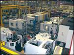
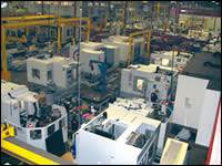
TWI, a division of Yamaha Motor Corp. USA that makes sport boats, uses state-of-the-art production techniques. The boat’s hull and deck, for example, are constructed of multiple layers of fiberglass with sandwich core construction reinforcements. The manufacturing process includes laser-guided robots that cut and drill each hull and deck to exact specifications, ensuring that each boat is built the same down to the smallest measurement.
As with all fiberglass construction, TWI first builds molds on which to shape the fiberglass parts. Molds are made of tooling fiberglass based on a high-density foam master part (called the plug). For each boat model, the company builds approximately 15 molds that last for the lifespan of the model, typically three or four years. During that time, the molds are often modified. This happens when a change is made to facilitate production or to meet a marketing requirement. Existing molds also are modified to spin off new models, such as the new SX230 and AR230 high output boats the company recently introduced.
Whenever molds are modified, TWI must update the manufacturing process to reflect the changes. This became more of a challenge after the company introduced two robots into its process. “The robots save time and are more accurate than manual manufacturing methods, but you need 3-D shape data to program them,” explains Denham.
The best way to acquire shape data is to import a CAD model of the part. An up-to-date CAD model is not available, however, when TWI is working with molds that have been changed manually. This situation requires reverse engineering to capture the new shape. In the past, TWI tried using the robot itself to capture the coordinates, manually positioning the robot arm to each desired position and recording the coordinates. This process took months and cost hundreds of thousands of dollars.
A Better Reverse Engineering Approach
TWI solved the problem with NVision’s laser scanning service. Laser scanning systems work by projecting a line of laser light onto the surfaces to be measured, while a camera continuously triangulates the changing distance and profile of the laser line as it sweeps along. The position and orientation of the scanning head also is continuously monitored by a highly accurate localizing device as the data is captured. A computer synchronizes these two inputs and translates the video image of the line into 3-D coordinates, providing real-time data renderings that give the operator immediate feedback on areas that might have been missed.
Laser scanners are able to quickly measure large parts while generating far greater numbers of data points than probes without the need for templates or fixtures. Since there is no contact tip on a laser scanner that must physically touch the object, the problems of depressing soft objects, measuring small details and capturing complex free-form surfaces are eliminated.
Instead of collecting points one by one, the laser scanner picks up tens of thousands of points every second. This means that digitizing even the most complicated parts can often be accomplished in an hour or two. Laser scanning can digitize parts that are so complex, it would be impractical to digitize them one point at a time.
Finally, the software provided with the scanner greatly simplifies the process of moving from point cloud to CAD model, making it possible in minimal time to generate a CAD model of the scanned part that faithfully duplicates the original part. The software also can be used to compare the original design geometry to the actual physical part, generating an overall graduated color error plot that shows at a glance where, and by how much, surfaces deviate from the original design. This goes far beyond the dimensional checks that can be performed with touch probes.
Laser Scanning Service Delivers Accurate CAD Data
Rather than purchase its own laser scanner, TWI hired NVision’s service bureau to reverse engineer some of the shapes for the new SX230 and AR230 high output boats. “We hadn’t allocated money to purchase a scanner so we decided to use a scanning service,” says Denham. “We have used other companies in the past and were not happy with the results. For example, one company came and did some scans, but could never get the data to mesh together. We chose NVision because their demonstration delivered the best results.”
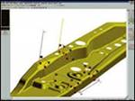
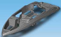
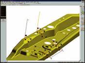
NVision representatives came on-site and scanned the molds. This process took one week. They spent another three weeks converting the point cloud data derived from scanning into a 3-D surface model using special software. Then they translated that model into the Solidworks CAD format that TWI uses—creating a highly accurate 3-D model that TWI was able to use for robot programming. “The people from NVision made sure the CAD data was good, they diagnosed the part and handed the part off to us,” says Denham. “We were very happy with their work.”
TWI plans to use NVision’s services again in the future, but will use a conversion process that creates an intelligent Solidworks file. “This will give us a smaller data file that includes the history of how the part was built, and it will be an intelligent model that defines the features on the boat,” Denham adds.
Bottom-line Benefits of Laser Scanning Service
For TWI, the test of the accuracy of NVision’s work is how well parts fit together when new designs go into production. “NVision proved the accuracy of the data by showing us comparison charts from the point clouds to the surfaces, but the only way to be sure is to go into production,” says Denham. “We’re in production now and all the data we have gotten from NVision has been accurate. By programming the robot based on the CAD model, all the holes were drilled in exactly the right locations.”
Now that TWI has precise CAD data available for robot programming, the actual programming process takes much less time, so a process that took several months in the past is completed in about one month.
The cost of the on-site laser scanning, creation of surface models and delivery of the Solidworks CAD data was an estimated $65,000 for the SX230/AR230 boats. When the cost of robot programming and creation of a CAD model is added to that, the total cost to accommodate a shape change is an estimated $100,000—±60 percent less than the amount the company spent on robot programming in the past. As Denham concludes, “The NVision service makes good economic sense for TWI.”
Related Content
CT Scanning Helps Micro Molder Reduce Cost of First Article Inspections
CT scanning services performed by 3D ProScan, a division of NyproMold Inc. provides MTD Micro Molding with accurate, high-resolution internal and external measurements performed about seven times faster and at significant cost savings.
Read MoreHow to Achieve Automated Measurement With Advanced Touch Probes and Laser Systems
A combination of lasers, probes and software help moldmakers automate in-process cutting tool and workpiece measurement.
Read MoreTechnology Roundup: New/Improved Technologies You Don't Want to Miss
With all the technology joining the market, moldmaking is a versatile, ever-evolving industry. As such, this technology roundup has no specific theme — it features a variety of products for applications and solutions across the industry.
Read More2024 Moldmaking Insights: A Year in Review Part 1
A look back at the top moldmaking trends of 2024, as revealed through MMT's analytics. This review highlights the most popular technical articles, case studies, tips and best practices that captured the industry's attention over the past year.
Read MoreRead Next
Pushing the Traditional Design Envelope with Hybrid Modeling
The complementary relationship between existing CAD technology and digital shape sampling and processing has led to a process called hybrid modeling, which combines the strengths of scan-based measurement with feature-based modeling.
Read More3-D, Non-Contact Scanning for Inspection: Info for Moldmakers
Understanding the differences and similarities between CMM and 3-D scanning allows moldmakers to adapt to, apply and leverage 3-D scanning technology within their shop environment.
Read MoreArm-Wrestling Unique Measurement Problems
A look at the advantages of a portable coordinate measuring machine in mold design and manufacture.
Read More

