Arm-Wrestling Unique Measurement Problems
A look at the advantages of a portable coordinate measuring machine in mold design and manufacture.
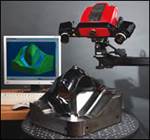
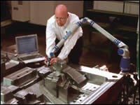
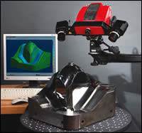
Coordinate measuring machines (CMMs) are devices used to measure the length, width, height and geometric features of three-dimensional objects in terms of X, Y and Z coordinates (see Figure 1). Because traditional CMMs are heavy, stationary devices, it is necessary to move the objects to be measured to the machine. Portable CMMs were developed to meet the need for coordinate measurement that was portable and reliably accurate in the harsher environments typically found in industry. The best articulated arm CMMs are rugged, portable, flexible, and can accurately and repeatedly measure objects down to .0002".
Users can mount the device directly to the machinery that makes the part, then simply guide the touch-probe along the surface of the object, and the arm’s laptop computer simultaneously illustrates the 3-D measurements on-screen and records all of the data. In essence, it creates a 3-D blueprint of a part—or of machine components that make parts—so you can perform inspections, tool certification, CAD-to-part analysis or even reverse engineer custom parts.
Applications
Applications that might favor this tool include:
Digitizing Sheet Metal Templates
Sheet metal shops often convert their conventional cutting templates to programs for operating new laser and waterjet cutting machines as well as automatic punching machines.
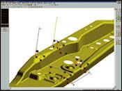
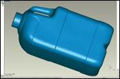
The conversion process involves scanning the contours of the pattern and sending the digitized data as a .dxf file to a post-processor, which automatically converts the information into an NC cutting program (see Figure 2). What would have required an entire day of programming takes a fraction of the time with the help of a portable CMM.
Updating Old CAD Drawings
After the sheet metal cutting program has been created, the digitized data also is used to create an updated part drawing in AutoCAD software. Very frequently, these templates have undergone a series of modifications on the shop floor to improve manufacturability, without being recorded in the software file. The result is that no accurate drawing exists. Updating the drawing with the digitized data ensures that it matches the actual template.
This approach also works well to update drawings of tooling and fixtures, which are often frequently modified during pre-production. Measuring the production setup and feeding the data back to the CAD system to update drawings can save hours of trial and error work years later when the tooling needs to be repaired. The articulating measurement device is ideal for this because the tooling can be measured without having to disassemble it.
Making the Perfect Parabola
The performance of an eight-foot diameter, molded satellite dish depends on how closely its contours approximate a perfect parabola.
The manufacturer could not afford a CMM costing several hundred thousand dollars to measure their molds. Instead, they tested the product functionally by placing a microphone at the focal point of the dish and analyzing the noise level of captured sound. Based on the results, the mold would be modified and a new dish molded and tested until, after many iterations, the cleanest range of sounds was captured. This was a painfully long and arduous process.
Today, mobile measurement equipment is used to scan the mold surface. The surface contours generated by the measurement system are superimposed over a perfect parabola in computer-aided design software. The disparity between the two images indicates where the mold is either too deep or too shallow, and by how much.
To correct the problem, mobile measurement equipment is used again to find and mark areas on the mold that need to be re-worked.
Scanning Contoured Edges
Most CMMs only collect discrete points at predetermined intervals. A major advantage of a portable CMM is that it can be used to manually scan continuous surfaces.
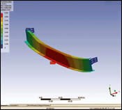
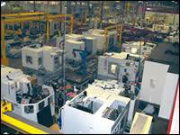
A recently developed application of mobile measurement equipment for an aerospace manufacturer involves measuring parts trimmed by a large robotic router machine. Most of the laminated composite parts within the final assembly need to be trimmed to very exact dimensions (see Figure 3).
The robotic cutting program for the part is modeled in CATIA software. Inspection of the first piece verifies the accuracy of the cutting program. The conventional process called for inspectors to use templates cut to shape to verify the trim. This process could take an entire day. Today, it is possible to set up the mobile measurement equipment, scan over a thousand points along the entire periphery of the complex 3-D part, and analyze the data in CATIA within about two hours. Accuracy is improved, and the NC programmer gets feedback on his part the same day.
Re-Engineering Existing Parts
An aerospace manufacturer is currently involved in a number of projects that require the re-engineering of existing parts into CAD software. This work involves modifications to long-standing parts that currently meet customer specifications.
Originally designed on the board, perhaps more than a decade ago, these parts have a history of design and tooling modifications not necessarily noted on the drawings. The portable CMM rapidly scans the parts and digitizes their data, which are sent to the computer system in a format that is readily converted into a 3-D computer design of the part.
Summary
As you can see, portable coordinate measuring machines are the tools of choice throughout the field of moldmaking. From certifying that a mold produces accurate parts and providing quality control documentation for traceability to reverse engineering new products. They have the accuracy, adaptability and capability to give successful manufacturers the data they need to improve their products and processes.
They also can save money. Measuring fixtures in-house saves transportation costs and measuring fees. Moreover, a portable CMM costs much less than a stationary CMM that has a comparable measurement envelope. To check the same size mold on a CMM, you would need to invest four or five times more in the CMM than what would be spent on a portable CMM.
Related Content
What Is Scientific Maintenance? Part 1
How to create a scientific maintenance plan based on a toolroom’s current data collection and usage.
Read MoreThe Ins and Outs of Hot Runner Temperature Control
A training checklist that explains the why and how of proper hot runner temperature control and system management.
Read MoreLaser Welding Versus Micro Welding
The latest battle in finely detailed restoration/repair of mold materials.
Read More5 Hot Runner Tips for Moldmakers and Molders
Best practices for initial hot runner tryouts and effective preventive maintenance.
Read MoreRead Next
Taking Technology to New Heights
White light, non-contact scanning system adds new capabilities including real-time inspection.
Read MoreMold Development with Digital Shape Sampling and Processing
Use digital shape sampling and processing to produce more accurate molds, free up machine time for CNC systems used in milling and drastically cut the time it takes to develop a new mold.
Read More3-D, Non-Contact Scanning for Inspection: Info for Moldmakers
Understanding the differences and similarities between CMM and 3-D scanning allows moldmakers to adapt to, apply and leverage 3-D scanning technology within their shop environment.
Read More
