Pushing the Traditional Design Envelope with Hybrid Modeling
The complementary relationship between existing CAD technology and digital shape sampling and processing has led to a process called hybrid modeling, which combines the strengths of scan-based measurement with feature-based modeling.
Over the past decade, digital shape sampling and processing (DSSP) has evolved to comple-ment CAD and product development, helping thousands of customers convert 3-D scan data into digital models for design, analysis, manufacturing and visualization.
The ability of DSSP software to automatically generate NURBS surfaces from point-cloud data enables users to accurately capture and reconstruct the shape of a physical part. This capability has proven ideal for the following applications:
- Capturing physical designs and prototypes
- Reproducing legacy parts, molds and tooling
- Replicating complex and organic shapes
- Preparing as-built models for moldmaking and CAE applications
- Enabling mass-customization of unique components
- Preserving historical and cultural artifacts
In recent years, the complementary relationship between existing CAD technology and DSSP has led to a process called hybrid modeling, which combines the strengths of scan-based measurement with feature-based modeling.
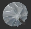
This article discusses the advantages of the hybrid approach, and shows how to use it to create a native, parametric model of a complex pump impeller that can be used to produce a mold for casting and manufacturing.
Combining Strengths
Traditional CAD models are created by defining a construction sequence of 2-D and 3-D entities (features). Described as prescriptive modeling, CAD operators draw upon their skill and experience to create new designs by specifying the parameters of these entities to control the resultant shape of the object. The completed parametric model offers great flexibility for generating multiple variations that can be used for design iterations and rapid experimentation with form and function (see Figure 1).
While the traditional CAD approach is good when modeling from scratch, it has shortcomings when a user is faced with the challenge of reconstructing a complex surface. It takes a lot of time and effort, with no guarantees of an accurate model. In some cases it is almost impossible to use a feature-based approach to reconstruct surfaces, due to the difficulty in identifying and quantifying the parameters that control the object’s shape.
Hybrid modeling provides a solution to the shortcomings of traditional CAD for reconstructing complex surfaces. Basic reference geometry—such as datums, curves and primitive features—can be measured and extracted from the 3-D scan data. The process moves easily between CAD and DSSP software, leveraging what each program does best.
Capturing the Physical Part
The first step in the process is capturing the existing physical part. The impeller that serves as the example is scanned by a “white-light” scanning system that uses two high-resolution cameras to capture projected fringe patterns on the surface of the part. These patterns are analyzed to triangulate millions of points on the part and generate a point cloud.
Due to the shiny surface of the part, a powder coating is applied to reduce reflectivity that would interfere with the projected patterns. The complexity of the shape requires that multiple scans be taken from many different positions to provide line-of-sight to all of the surfaces of the impeller (see Figure 2).
An array of registration targets are placed on the impeller to aid in aligning the multiple scans. Using a technique known as photogrammetry, the center points of the targets are automatically detected from the high-resolution camera images. The collection of visible points as seen from any position provides enough information to align each scan.
The scanner captures 15 million points from more than 20 scans. The scans are aligned and merged to create a polygon model (see Figure 3).
Cleanup and Repair
After importing the scan data as an STL model, the next step is to clean and repair the data using automated processes within the DSSP software. Typical cleaning procedures include removing extraneous data, noise reduction, decimation of data to reduce file sizes, filling holes and repairing intersections. In this example the entire polygon model was repaired, but in many cases only portions of the model that will be used during the parametric reconstruction process need to be cleaned (see Figure 4).
Extracting Curves and Datums
After creating the model in DSSP software, we start reconstructing the shape of the hub by detecting the center axis of the impeller, defining the hub profile with an extracted curve, and then generating a surface of revolution with the curve revolved about the axis.
The axis can be found by selecting the outer perimeter surface area of the impeller. This area should be perfectly cylindrical by design, and will generate a stable datum axis. An alternative would be to use a selection of the hub surface area to calculate the axis from the rotational surface.
The next step is to create the profile curve that will define the shape of the hub. In this case a simple planar cross-section curve cannot be extracted, as the blades interfere with the cross-section of the hub. Fortunately, we can draw upon the tools in our CAD system and use another approach: a variable section sweep. We can generate the surface by extruding a half-circle along the hub axis, and control the diameter of the half-circle with a non-planar curve extracted from the hub surface (see Figure 5).
The bottom surface of the impeller does not have any obstructions from the blades, so a simple planar curve can be extracted and used to create a surface of revolution.
To create additional parameters for controlling the shape of the surfaces, consider using the orthogonal edge boundaries of the swept surfaces to create new, idealized curves.
Combining Free-Form Surfacing
The blades are the most complex elements of the impeller’s design. These surfaces are difficult to measure or define with basic parameters. Using NURBS surfacing in DSSP software, however, the blades can be quickly surfaced and imported as IGES or STEP features (see Figure 6).
After a single blade is imported, it can be replicated (or “patterned”) around the imported datum axis to create multiple blades on the hub surface. The entire import and pattern process is again repeated with the second splitter blade. Rather than define the spacing between the blades as a direct angular measurement, a parameter is defined that relates the angular spacing to the total number of blades. This will allow us to easily change the number of blades while preserving the appropriate blade spacing.
After incorporating the blade surfaces into the solid model, a parametric radius is defined at the surface intersection. This radius can be adjusted at any time in the future. Again we can draw upon the wealth of tools in the CAD system to define many other blends, including variable radius and rolling ball.
Trimming and Blending
After all of the blades have been positioned, additional datums and curves are defined to perfect the contour along the outer surfaces of the impeller. Again, a non-planar profile curve is extracted from the DSSP software, and a variable section sweep is used to generate the surface to trim the outer surface of the blades (see Figure 7).
A cylindrical surface is then generated to trim the outer surface of the entire impeller. This cylinder is centered on the extracted datum axis, and its diameter can be measured by constructing a 3-D feature cylinder from the polygon surface. After trimming the outer cylinder, we can be assured that our design has produced a perfectly centered and symmetric impeller.
Full Parametric Model in One Day
The final model meets all of the design parameters, and is verified to be a closed solid. Using computer-aided inspection software, we can compare the final CAD model to the original scan data to verify its accuracy (see Figure 8).
The hybrid modeling method provides full parametric control over the shape of the hub surface, the radii of the blends, and the number and spacing of the blades. The complete process, including scanning, repair and modeling, took less than a day to complete.
With some alterations, the 3-D model generated with hybrid modeling is ready for use in creating a casting mold. The model can also be used directly to power a rapid prototyping system that speeds mold production in a process called quick casting.
The Benefits
The hybrid modeling process provides several key benefits:
- It leverages existing 3-D investments. CAD vendors have invested thousands of man-years to create highly evolved systems for digital design and creation. Hybrid modeling takes advantage of your existing modeling system—and the skills of your CAD users and experts—and augments it with 3-D measurement and rapid surfacing capabilities.
- It enables new designs to be created in less time. When compared to traditional CAD techniques, the hybrid measurement and modeling approach can greatly reduce the amount of time required to replicate an existing design. In some cases the hybrid approach can be completed in a matter of hours as opposed to days or weeks using conventional techniques.
- It produces native parametric CAD geometry. Using the strengths of the CAD system, various aspects of the design can be parametrically driven by numerical values or other constraints such as assembly-mating conditions. Many file I/O translation issues are avoided, as the core of the geometry has been produced within the user’s CAD system.
- It generates accurate results. Freeform surfaces can be generated from point clouds containing millions of sample points. This technique reproduces subtleties in surface structures that would otherwise be lost. The process is highly repeatable, as acquisition of scan data is less operator-dependent than typical measurements performed by hand.
Summary
Hybrid modeling combines digital shape sampling and processing with the power of computer-aided design to provide an innovative solution for parametric reverse engineering.
CAD systems will continue to serve as the nexus of 3-D digital design and creation, complemented with tools such as DSSP software for measuring 3-D scan data and modeling complex surfaces. This combination enables users to create native, parametric models quickly and accurately. Users are able to infuse new capabilities into CAD models, leverage familiar workflows, and take advantage of existing knowledge to push the envelope of digital design.
Related Content
Four Micro Tooling Considerations
Issues involving gating, ejection, mold splits and direction of pull are of special concern when it comes to micro tooling.
Read MoreTips for Tackling Mold Design, Machining, Cutting Tool and Wear Challenges
Tips for tasks ranging from reducing risk in part design and taking advantage of five-axis machining to refining cutting tool performance and reducing wear with guiding and centering systems.
Read MoreMold Design Review: The Complete Checklist
Gerardo (Jerry) Miranda III, former global tooling manager for Oakley sunglasses, reshares his complete mold design checklist, an essential part of the product time and cost-to-market process.
Read MoreHow to Analyze and Optimize Cutting Conditions to Reduce Cycle Time
Plastic injection mold design and manufacturing company puts NC program optimization software module to the test. The results were surprising.
Read MoreRead Next
White-Light Scanning Validates Faster, Better Processes for Molded Auto Interior Trim at Eifel Inc.
The use of white-light scanning and photogrammetry ensures accuracy of tool building programs.
Read MoreChicago Mold Engineering: In The Spotlight
Focusing on a niche in the automotive headlap reflector market—coupled with the most advanced technologies and mold manufacturing techniques—lights the way for this moldmaker’s 2007 Leadtime Leader Award: Large Shop.
Read More3-D, Non-Contact Scanning for Inspection: Info for Moldmakers
Understanding the differences and similarities between CMM and 3-D scanning allows moldmakers to adapt to, apply and leverage 3-D scanning technology within their shop environment.
Read More
