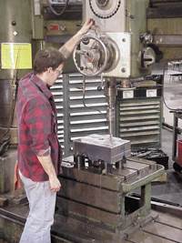
Workholding System Reduces Set-up Times, Yields Flexibility
With the FCS system, mold shop is saving time in areas of workpiece preparation and locational pickup in the machining centers.
CS Tool Engineering, Inc. (Cedar Springs, MI)—a supplier of plastic injection and compression molds in the automotive, furniture, aerospace and consumer goods markets (and 2010 Leadtime Leader Honorable Mention)—was looking for a flexible workholding system since the company deals with a variety of workpiece sizes that would also reduce set-up times. This mold manufacturer found what it was looking for in the FCS System by Single Source Technologies, Inc. (Auburn Hills, MI).
According to CS Tool Operations Manager Donald Snow, set-up times have posed a challenge relative to any machining process—and they take away from productive machining time. “We moved to adding a new HMC with a two-pallet set-up by which the workpiece could be set-up and removed from one pallet while the spindle is machining on the other station's pallet,” Snow explains. “In working with a horizontal spindle machine, just using the conventional strap clamp set-up can be a challenging task as you attempt to position and clamp the work with only one machine operator. Starting out with our new HMC, we struggled with conventional clamping and then indicating the block to be square with the machine travels. A measuring probe in the spindle can do this without the need to square up your block, but this also takes some operator time as the workpiece is living in an unknown position on the pallet.”
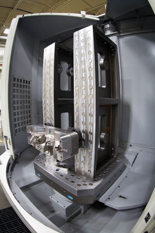
The modular FCS system is a grid-based system that uses each locating point as a locator and clamp point, Single Source Technologies Tooling Consultant Jim Minock points out. “The main reference grid is set at 50mm spacing with a precise positional tolerance,” he comments. “Usually, on a single-plate application, the center hole becomes the zero point. This establishes the physical workspace machine x-y zero. Since most toolpaths are programmed using CAM software, the workholding can be planned in the virtual workspace in advance for each machine or operation.”
The marriage of the virtual workspace to the physical one has a level of precision of 6 microns, Minock continues. “The FCS mounting is planned by the designer/programmer, who decides where to locate the work piece and the FCS clamps to the grid,” he says. “When the job gets to the machine, the clamping units are positioned; the part placed on the clamps and the job is ready to run. There’s no running around to find nuts, rods or straps, no need to pick up the part for x-y zero.”
Minock adds that the FCS system provides systematic and planned workholding to reduce set-up time and improve the flow of work through the shop. The process to implement the FCS system into a shop is simple, he says. “The mounting in the part is simply a threaded hole and a counter bore usually on 4 points. The points can be placed anywhere on the bottom of the part to avoid part features, ejector holes, or water lines, as long as they stay on the 50mm grid.” And, once the mounting holes are machined, the counter bores become the fixed x-y reference point for the life of the part. The part can be moved from machine to machine and set up quickly without the need to “find” x-y zero.
Snow reports that the accuracy and repeatability in using the FCS system has not been an issue as CS Tool machinists move different workpieces from machine to machine with minimal positional checks. “The accuracy is in your grid system of FCS holes whether you purchase or fabricate your grid plates,” he notes. “Currently we are experiencing accuracies of less than .001" total. One needs to remember that this system still respects good set-up principles relative to the accuracy one is trying to achieve. And, the system has simplified the aforementioned position and strap clamp dilemma.”
CS Tool is extremely happy with the system’s flexibility and simplicity—coupled with the fact that the company is not locked into a “manufactured” pallet size, Snow says. “The FCS system can be used on any size mold block and/or component,” he states. “Some of the other systems out there do not have the size flexibility that FCS offers as it relates to dealing with varying workpiece sizes.”
Additionally, the system has been solid modeled so that the CNC programmers can "design" the set-up knowing where the workpiece will be in the machine and not have to program around where the workpiece may have been conventionally clamped, Snow notes. “With the FCS system, we are saving time in areas of workpiece preparation and locational pickup in the machining centers. People may challenge the time it takes to machine the threaded hole and qualified counter bore necessary in using FCS, but once those holes are installed you have a feature that can be used repetitively and accurately in different machines throughout the build process.
“Originally we set out to equip our new HMC with the FCS system and soon found that we had more machining applications than the one machine had capacity and/or size,” Snow continues. “We set out to equip another smaller VMC with the fabrication of another set-up of grid plates and before we could get that machine set up, our programmers and machinist had those grid plate pieces mounted in other machining centers to simplify the clamping and machine process. Having the ability to machine five sides of your workpiece in one set-up, or rotating a block with a second or third set-up without picking up in a three-axis machine, is a big time saver—and the accuracy and repeatability is there.”
Snow adds that while the initial cost of the system is not an inexpensive undertaking, the reduction in setup time and flexibility the systems provide is a paradigm shift in current processing methods.“At a minimum we can save 50 percent of our set-up time,” he explains. “Our goal is to have this FCS system of grid plates in all of our major pieces of equipment—from the boring mill, gun drill and machining centers to the EDM and CMM. Think of the hours that can potentially be saved—and turned into cutting time!”
For More Information:
CS Tool Engineering, Inc. / (616) 696-0940
donsnow@cste.com / cste.com
Related Content
Moldmakers Deserve a Total Production Solution
Stability, spindle speed and software are essential consideration for your moldmaking machine tool.
Read MoreHow to Eliminate Chatter
Here are techniques commonly used to combat chatter and guidelines to establish a foundation for optimizing the moldmaking process.
Read MoreDevelopments in High-Speed Machining Technology
There have been many exciting developments in high-speed machining relative to machining centers and controls, tooling and CAD/CAM systems.
Read MoreRead Next
Increase Profitability Through Magnetic Workholding
Milling magnets offer moldmakers the convenience of fully accessible five-axis machining in one setup with the benefits of cost reduction and tolerance improvements.
Read MoreReasons to Use Fiber Lasers for Mold Cleaning
Fiber lasers offer a simplicity, speed, control and portability, minimizing mold cleaning risks.
Read MoreHow to Use Strategic Planning Tools, Data to Manage the Human Side of Business
Q&A with Marion Wells, MMT EAB member and founder of Human Asset Management.
Read More
