Increase Profitability Through Magnetic Workholding
Milling magnets offer moldmakers the convenience of fully accessible five-axis machining in one setup with the benefits of cost reduction and tolerance improvements.
Machining practices have come a long way in the last 15 years. Parts that previously took a day to machine can now be machined in hours. Increased productivity through faster machines and new cutting tools has enabled companies to be more competitive. However, many of these companies are still using the same clamping methods that they used in the 1920s - toe clamps and vices. And although machines are faster, setup time has not changed significantly. In addition, machines today have the ability to machine in up to five axes, yet most conventional fixturing does not give total access to all five faces of a part.
With its unique properties, magnetic workholding is the next significant step in increased productivity. Users of magnetic workholding estimate that setup reduction averages 50 percent through a reduced number of setups and a reduction in overall setup time. In addition, most users of magnetic workholding also estimate that payback takes less than a year. Until recently, the use of magnetic workholding technology had been basic, but new innovations like powerful permanent electro magnetic setup blocks and new, more powerful permanent milling magnets have greatly increased their usefulness to moldmakers.
What Are Magnetic Chucks?
There are three types of magnetic chucks: permanent, electro magnetic and permanent electro magnetic. Permanent magnets switch on and off through the alignment of permanent magnets within the chuck to the mild steel surface on top of the chuck. Permanent magnets are restricted in their clamping force by one's ability to overcome the magnetic resistance in turning the chuck on and off. Historically, permanent magnets were only used for grinding and EDM because of the limited clamping forces as a result of the magnetic resistance.
Electro magnetic chucks use a constant supply of electric current through a coil around a soft iron core to create the magnetic field perpendicular to the coil. Electro magnets can generate large magnetic fields, but if power is lost, so too is the magnetic clamping - making them impractical for pallet changers and machining centers. In addition, it is important to note that electricity through an electro magnet generates significant amounts of heat within the chuck and on the surface.
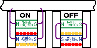
Permanent electro magnetic workholding has made significant strides in the past 10 years, especially with the advancements in neodymium magnets. Neodymium iron boron (NdFeB) magnets are smaller and more powerful than other types of permanent magnets. Therefore, magnetic fixturing is more powerful and more compact. In addition to neodymium, permanent electro magnets also use alnico magnets as the magnetic switch. The magnet can be turned on or off by changing the polarity through a pulse of electric current. This cycle takes less than one second. Permanent electro magnets only require electricity to turn the magnet on and off - no electricity is required to maintain the magnetic field (see Figure 1).
What's New
In 2001, two new types of milling magnets entered the market - magnetic setup blocks and permanent milling magnets.
Magnetic Setup Blocks
The first was permanent electro magnetic setup blocks. As milling magnets turned the workholding industry upside down, so too will permanent electro magnetic setup blocks forever change conventional fixturing. Permanent electro magnetic setup blocks are available in 110, 220 and 440 volt. A setup block only supports a permanent electro magnetic setup block supports and clamps. Permanent electro magnetic setup blocks combine the holding power of a milling magnet and the flexibility of a setup block into one.
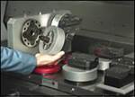
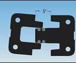
Magnetic setup blocks are the latest advancements in permanent electro milling magnet technology. They are designed to offer greater flexibility than the conventional milling chucks without sacrificing holding force. Previously, mold shops had to purchase a milling chuck of a given size if they wanted to use milling magnets. If the part to be machined was 1/3 of the chuck size, then 2/3 of the chuck went unused. Or if the part exceeded the size of the chuck, there was no means to stretch the chuck for even support. The only option then was to either do it the old way or buy another chuck. The introduction of magnetic setup blocks gives the shop greater flexibility and profitability because each module offers the same clamping force as a pair of balanced poles on a milling chuck (see Figure 2). The bonus is that if a job requires fewer modules, then the remaining modules can be used on another machine - hence there is no wasted magnetic area. Because the modules are permanent electro, one controller can fire infinite setups.
On the other hand, if a larger part needs to be machined, the modules can be spread apart for better distribution of the magnetic force (see Milling on a Magnet for restrictions). Additional modules can be added as needed to increase the coverage area. Unlike conventional milling chucks, which do not allow for slight movements in pole placement, magnetic setup blocks can be located wherever the best contact area is available. When mounted to a sub-plate that is drilled and tapped on one-inch centers, placement is easy. In fact, a setup on a sub-plate can be moved from a drilling or milling operation to a grinding operation without demagnetizing the modules. The grinder would clamp to the sub-plate and the modules would continue to hold the workpiece.
Permanent Milling Magnets
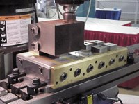
The other new item is a permanent milling magnet that offers significant holding power at a reasonable price. Permanent milling magnets made their debut in 2001 and can be 3.5 times more powerful than traditional permanent grinding magnets. They are ideal for small VMCs and knee mills. Because of the magnetic resistance, each set of poles is individually magnetized and is therefore restricted in size. It is believed that using permanent milling magnets will revitalize the use of traditional knee mills. The knee mill is an American standard, but has not been used as often in recent years. With the introduction of a permanent milling magnet, the knee mill now has the ability to handle larger parts - such as those that overhang the table - and multiple parts. Previously, once a vice was placed on the bed of a knee mill, only one part could be machined at a time, costing much time in setup. A permanent milling magnet does not require electricity and can be easily moved. It also has the ability to utilize top tooling like pole extenders, back parallels and magnetic angles (see Figure 3).
Milling on a Magnet
What was once considered a black magic has become a more calculable science. Still, many variables affect the clamping force of a magnet. Some of these variables include: material composition, surface finish, contact area, vibration and cutting forces. An important fact to understand about magnetic clamping is that all magnets have 100 percent clamping force directly away from the face of the magnet, but only 20 percent clamping force against slide forces. This is the coefficient of friction. Often people will improperly judge a magnet's ability to hold for machining by striking a magnetically clamped part on the side with a mallet.
Unfortunately, this does not accurately replicate machining forces. Cutting forces are usually multi-directional - including down into the table. Serious manufacturers of milling magnets offer cutting formulas to aid in the determination of viable cutting parameters. In some cases, cuts on a magnet will exceed conventional clamping due to reduced vibration or increased holding force. In other cases, cuts may have to be reduced for magnetic clamping. In these cases though, the additional cut time may be offset by either a reduced number of setups or increased feedrates. The addition of physical stops can increase stock removal by up to two times over not using stops.
Steel
Mild steel is the most receptive material to magnetic clamping. Tool steels are 15 to 30 percent less permeable and cast iron is 30 to 50 percent less permeable than mild steel. Therefore, moldmakers need to be aware that cutting calculations need to be adjusted when other material, such as tool steel, are considered. Magnetism does not like air gap, whether caused by surface finish or vibration. Air gap is any space between a workpiece and the surface of a magnet caused by uneven workpieces, rough finish on a workpiece, nonmagnetic spacers like shims, or vibration. Therefore the better the surface finish and proper pole placement - to avoid vibration - the greater success one will have using a magnet.
Finish
Rough finish material can be milled on a magnet if the proper cutting calculations are used. Some magnets have greater magneto motive force (MMF) - a magnet's ability to bridge air gap - and are more suited to regular usage on rough surfaces. Otherwise, a simple down rating on the cutting forces will suffice. Keep in mind, however, that a permanent electro or a permanent milling magnet will not suddenly lose its clamping force. Therefore, if a magnet is overpowered by a cut, the part simply slides across the face of the magnet. This prevents serious damage to the part, cutter and machine as well as injury to anyone near. If a cutter runs through a conventional clamp or if the clamp or vice becomes loose, the part will fly.
Vibration
Vibration on a magnet can be caused by numerous conditions. One cause is too much overhang or too much space between poles. As a rule of thumb for standard cutting calculations, overhang should not exceed the thickness of the part, and the distance between the poles should not exceed 2.5 times the part thickness. Another cause for vibration is an air gap caused by a non-flat workpiece or a rough surface finish. Some magnets offer self-leveling devices to address a non-flat workpiece. Rough surface finish is best handled by adjustments in the cutting parameters or through the uses of a magnet designed for rough finishes.
Polarity
A critical point to understand regarding magnetic clamping is the area in contact with the magnetic poles. It is not the number of total poles in contact with the workpiece that determines the holding power, but rather the number of equal north and south poles (polarity) that are in contact that determine the clamping force. If the area of a part is in contact with more of one polarity than the other, the extra magnetic contact actually interferes with the ability to machine the part. Magnets offering magnetically balanced north and south poles combined make for easier setups.
Advantages
Magnetic clamping offers as many benefits for the small shop as it does for the production machining shop. Magnets can offer full access to all five faces of a part in one setup. For example, a magnet laid flat on a pallet of a horizontal mill will allow the machine to mill around all four faces and drill into all four faces in one setup - an ideal squaring up process.
In addition, the use of magnets also makes programming easier. No longer is there a need to coordinate clamp location with the program. Magnets reduce vibration, therefore tooling is freer to run faster and longer. Through the use of top tooling or modular poles, a block of steel can be faced, edged and drilled through in one setup. With greater access to a part, a machine can run longer unsupervised (lights out) - resulting in higher productivity.
Milling on a magnet benefits both VMC and HMC operators through setup reduction and improved safety as well as reducing the risk of losing your qualified locator by reducing the number of setups. Magnetic setup includes loading parts, indicating parts and energizing the magnet. Energizing a magnet requires less than one second of electricity. In comparison, many injuries during setups are a result of reaching while tightening a clamp, or of trying to support work on a horizontal machine while tightening a clamp.
Other advantages of milling on a magnet include consistent clamping force. Regardless of the strength of an operator, the clamping force of a magnet is a constant. Most milling magnets offer pole extenders to raise a part off the surface of the magnet. This allows not only for milling, but also for through drilling. There also are new individual magnetic setup blocks that can be located anywhere under a part and used as a milling magnet or a magnetic work support with conventional fixturing.
Positive Experiences
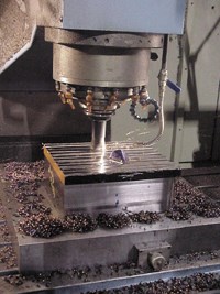
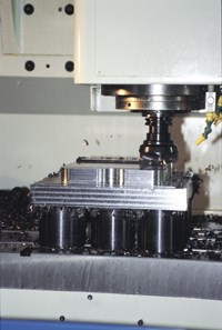
Precision Mold & Engineering Company (PME) (Benton Harbor, MI) - a moldmaking operation - has magnetic milling chucks on six of its VMCs and a set of magnetic milling modules for general shop use. PME finds the milling chucks to be a significant time saver in its roughing and finish operations (see Figure 4). Larry Shermak, PME's plant manager, calculates that PME has reduced its setup time by 50 percent by milling on a magnetic chuck. PME has found the milling chucks to be more powerful than expected. They offer flexibility all over the shop.
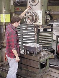
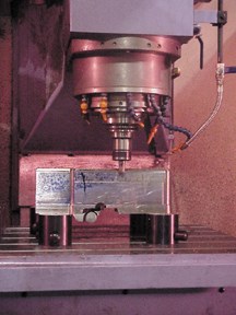
According to Shermak, the company will use the milling modules when it needs to work on the backside of an insert (see Figure 2). Previously, the company had to block it up and clamp it. The company could not achieve the flexibility with magnetic pole extenders. However, the magnetic modules allow it to use as many or as few modules as the job requires while the rest of the modules can be used on another machine. The modules have increased the workable area on other machines, such as the radial drill press (see Figure 5) when drilling and tapping holes. If need be, the company can collect all of its modules on one machine for another milling chuck (see Figure 6).
Milling chucks also offer other advantages. Milling chucks are better suited for dedicated machine use and for particularly heavy milling on large parts because milling chucks have only one detachable cord to the main chuck. Magnetic modules also have only one detachable cord to a junction box. From the junction box, individual coolant and chip resistant cables run to each module.
A fear that many shops have had over the use of milling magnets is what happens to the chips. Magnetic field depths vary by manufacturer, but can be as shallow as 0.400" deep into the part. As long as the magnetic fields are in balance, the residual magnetism throughout the part is insignificant. According to Shermak, "Chip control problems are about the same as with any other workholding method. Blowing the chips away with air or flushing them away with coolant are the typical methods to getting the chips out of the way. With magnets, the only chips that are left are ones within the flux height of the magnet."
When milling nonmagnetic material, shops properly trained in the use of magnetic workholding generally only return to conventional clamping methods when forced, such as on aluminum. Even with aluminum, magnet users often use their magnets to hold the vice, which holds the aluminum.
Magnetic workholding is the next significant step in cost reduction and tolerance improvement, and comes in a variety of systems for different applications. And as with any new technology, the key to making the most of your magnetic workholding is magnetic understanding and training.
Related Content
Solving Mold Alignment Problems with the Right Alignment Lock
Correct alignment lock selection can reduce maintenance costs and molding downtime, as well as increase part quality over the mold’s entire life.
Read MoreLive Tool Expansion for Cutting Tool Tightening Options
North American importer Platinum Tooling offers Heimatec live tools for the Hass BMT turret to ensure more rigid mold machining operations.
Read MoreZero-Point Workholding Systems Facilitate Workpiece Clamping Ease
IMTS 2024: HWR Workholding USA highlights its full line of SolidLine and InoLine workholding products with recent and existing solutions for turning and milling applications.
Read MoreTool Balancing Equipment Ensures Consistent Moldmaking Results
Zoller enables balanced toolholders, tool assemblies and grinding wheels using its »toolBalancer« series, providing high-quality surface finishes and extended surface life to spindles and cutting tools.
Read MoreRead Next
Streamlining Your Setup Operations with the Right Workholding System
Creating a powerful manufacturing cell from a one-minute palletization solution.
Read MoreHow to Use Strategic Planning Tools, Data to Manage the Human Side of Business
Q&A with Marion Wells, MMT EAB member and founder of Human Asset Management.
Read MoreAre You a Moldmaker Considering 3D Printing? Consider the 3D Printing Workshop at NPE2024
Presentations will cover 3D printing for mold tooling, material innovation, product development, bridge production and full-scale, high-volume additive manufacturing.
Read More








.jpg;maxWidth=970;quality=90)