Developments in High-Speed Machining Technology
There have been many exciting developments in high-speed machining relative to machining centers and controls, tooling and CAD/CAM systems.
Developments in high-speed machining centers can be understood by examining the main application fields of high-speed machining and the technological advancements arising out of the requirements in these fields. The major application fields can be classified as aerospace, automotive, die/mold and general manufacturing.
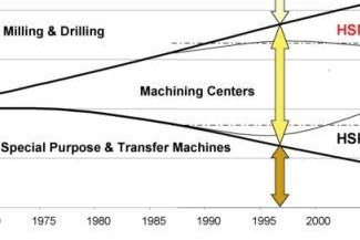
Figure 1: Market trend milling and drilling.
The worldwide market for milling and drilling machines is shown in Figure 1. Today the machining center market constitutes at least 60 percent of the total market, the remainder being taken up by special- purpose and transfer machines for large volume manufacturing, and by milling and drilling machines for small batch and one-off manufacturing. Within this market are high-speed machining centers used in small, medium and large batch production.
High-speed machining centers for large batch manufacturing are mainly in the automotive field and may be more strictly called high-speed positioning machines. The aim is to be able to move from point A to point B in the shortest possible time. These machines typically are horizontal machining centers with linear motor drives that offer rapid traverse rates of 100 to 120 m/min. and accelerations of 2 to 3g. Linear motors with their high feedrates and accelerations offer the benefits of higher productivity, which outweighs the drawbacks of higher energy consumption, higher heat generation and a higher cost of up to 30 percent compared to their ballscrew counterparts.
Spindles on machines for automotive applications need to be versatile to handle a variety of tools and have sufficient torque in the low ranges for drilling and tapping operations. Spindles here are generally in the 16,000 to 24,000 rpm range. New synchronous spindles that generate high torque at low speeds offer good potential for the future.
For high-speed positioning applications, hexapod and similar parallel kinematic or non-cartesian machines continue to be developed. Accuracy and repeatability, issues with controlling thermal effects, programming and control challenges and a large physical size for a small working envelope have kept these machines at an experimental stage. Nevertheless, interesting new designs appear at trade shows.
For one-off small and medium batch manufacturing there is a diverse range of high-speed machining centers. Aerospace machines are a class to themselves, as the application is high-speed profiling of aluminum and aluminum alloy aircraft structural components. The machines feature large travels where the benefits of linear motors are clear. High horsepower spindles, with speeds of up to 40,000 rpm, are designed for machining aluminum. The main objective here is optimizing metal removal rates by running at or near the resonant frequency of the machine and minimizing chatter.
Die/mold and general manufacturing applications pose a different set of requirements for high-speed machining centers. Complex 3-D shapes need to be machined with speed, accuracy and high surface finishes. Materials machined range from hardened steels, steels and aluminum to copper and graphite. With available tooling technology, practical feedrates in hardened steels are up to 8.0 m/min. and in graphite up to 12 m/min., beyond which there is material breakout.
For such applications, linear motors are beneficial in larger travel machines but, considering their cost and drawbacks, are not practical or economical for small to medium travel machines. These machines are equipped with ballscrews and today can achieve feedrates of 80 m/min. and up to 2.5g acceleration vectorially in three axes. As the materials are diverse and there is a wide range of tool sizes, a variety of spindles are offered with speeds ranging from 12,000 to 60,000 rpm. Depending on the application, a careful selection of the spindle is critical for success.
Developments in high-speed machining technology must therefore be considered relative to the field of application. What may be useful for high-speed positioning in an automotive application is not necessarily of significance for high-speed contouring in a die/mold application. The converse also is true.
New technologies are influencing small- to medium-sized, high-speed machining centers (up to 800 mm longitudinal travel) used in die/mold and general manufacturing applications, which constitute the majority of the high-speed machining centers sold in the market.
High-Speed Machining Centers - Construction
A popular method of construction for this class of high-speed machining centers is the bridge-type construction, a modified bridge construction or an overhead gantry system. Compared to a C-frame, which has an overhanging spindle and overlapping guideways for the table, the bridge design provides an optimal distribution of the moving masses and the spindle is rigidly mounted close to the guideways.
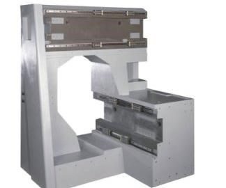
Figure 2: New monobloc bridge design in polymer concrete.
A drawback of the bridge construction, however, has been accessibility to the working area, both for the operator and for an automated loading device such as a pallet changer or robot. A new type of construction has solved this problem while providing many other benefits. Figure 2 illustrates a new bridge design in polymer concrete, which provides excellent accessibility to the working area from the front for an operator. The large opening allows good access for a pallet changer or robot. The pyramid-shaped construction with three-point support provides a stiff stationary structure to absorb the high acceleration/deceleration forces of the moving slides.
The polymer concrete construction, which is becoming increasingly popular for high-speed machining centers, provides six to 10 times better vibration dampening than cast iron. It also offers superior thermal stability, as the thermal conductivity of polymer concrete is 1/20 that of cast iron. Overall, the results are better tool life, better accuracy and surface quality, plus noise reduction.
The new polymer concrete construction also greatly reduces manufacturing costs and assembly times. Special bonding techniques allow complex structures to be created as a one piece or monobloc structure, eliminating any mechanical joining while providing superior rigidity. Such complex designs would be difficult to manufacture conventionally. Previously, guideway surfaces required cast in steel inserts to be machined or the surfaces themselves to be ground. Newly developed casting techniques enable guideway surfaces to be prepared with a straightness and parallelism of 0.005 mm in 1,500 mm for the direct mounting of linear guideways. No machining or assembly is required for any of the major structural components - truly a breakthrough in machine tool construction.
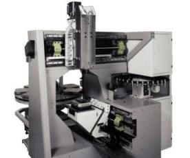
Figure 3: Assembled machine with integrated pallet changer.
The linear guideways, ballscrews, slides, motors and linear scales, etc., are mounted on the monobloc structure (see Figure 3). Other interesting features are that the linear guideways and ballscrews have permanent grease lubrication. No oil lines are required, there is no mixing of the oil with coolant, no oil disposal and the system is maintenance free. The spindle and feed motors are liquid cooled, thus conducting heat away from the structure. A laser tool measurement system serves to measure the length/radius of tools at the rotating speed, hence compensating for mechanical and thermal displacements of the spindle as well as thermal growth of the toolholder.
Automation
With 8,760 available hours in a year, there also is a growing requirement to automate high-speed machining centers, as with other machines in the shop, to get the maximum capacity utilization out of the equipment. With improved reliability and security of the high-speed machining process, machines are being designed to run around the clock. There are still processes that are better run attended - for example, roughing a mold cavity with an insert-type tool - while others such as finishing operations can run unattended. Finishing with a fine step-over can eliminate or reduce the requirement for polishing operations. Therefore to be able to run multiple jobs through the same machine is a requirement.
The first step toward this is a quick-change setup system or a palletizing system on the machine. The pallets can be changed quickly in and out of the machine, enabling multiple jobs to be processed through the machine. The pallets also have a common reference system as they can be transferred from machine to machine or process to process. The next step is to automate the loading and unloading of the pallets with a mechanical arm - either a pallet changer or a robot - when the requirement is to serve multiple machines.
Figure 3 illustrates a high-speed machining center that offers a table chuck and pallet system in lieu of the conventional machine table as a standard feature. The machine also is offered with a seven-position pallet changer as a standard feature. No longer is the pallet changer or a robot a feature for production machines. It is a necessity to utilize machines around the clock and get the maximum return on investment.
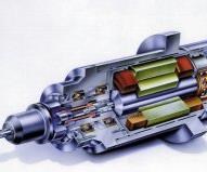
Figure 4: Integral motor spindle with hybrid ceramic bearings.
While various types of spindles are being developed, integral motor spindles with hybrid ceramic bearings remain the workhorse for high-speed machining (see Figure 4). A variety of sensors have been developed to enhance the performance of spindles and make them smarter. An acceleration sensor at the bearings allows vibration monitoring under cutting conditions. If the vibration exceeds a certain threshold value, the machining parameters such as speeds, feeds and radial and axial depth-of-cut can be altered to reduce vibration levels. A vibration level of less than 2g RMS provides better bearing/spindle life and also tool life.
Thermal and mechanical displacements of the spindle shaft remain a characteristic of high-speed spindles that is not well understood or accepted. An axial movement sensor can now monitor these displacements, which can be automatically compensated in the control.
A new spindle diagnostic module built into the spindle can record data on the use of the spindle during its life cycle. For example, the vibration levels can be recorded, and if these were consistently over the threshold value, a shortened spindle bearing life can be accounted for. Data also can reveal if the spindle was crashed, which can be useful to settle warranty issues. The data can be output from the spindle via an infrared interface. Data can be recorded for 100,000 hours.
Spindles also are being offered with greater capabilities of speed and torque. A new 32 kw, 30,000 rpm spindle provides 22 Nm low-end torque with the capability of handling tools up to 25 mm, while a new 8.5 kw 60,000 rpm spindle is intended for working with light metals and graphite with small tools up to 8.0 mm in diameter.
Controls
While advances are taking place in controls for high-speed machining centers in terms of block processing times, improved motion control algorithms, look- ahead, memory and network capabilities, an interesting development is a new intelligent process control system.
When high-speed machining complex3-D contours, it is usually a question of optimizing three target values: speed, accuracy and surface finish. For example, when roughing a mold, the priority could be speed. When finishing a small high-precision electrode, the priority could be accuracy. When finishing a blow mold or an injection mold cavity, the priority would be surface finish. Achieving these target values according to the application requires modification of hidden and usually inaccessible parameters called machine performance settings. They consist of hundreds of CNC parameters such as servo loop gains, axis jerk values, smoothing filters, etc., which have a tight relation to each other. Today, machines are optimized for one standard milling condition.
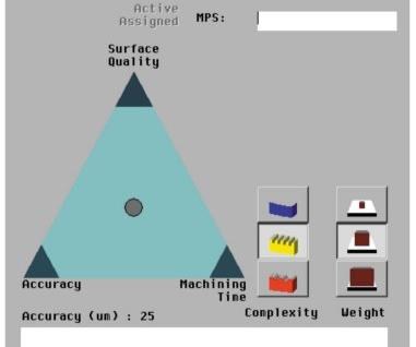
Figure 5: Expert control system.
With the new expert control system, the operator is able to optimize the machine performance settings with an easy-to-use graphical interface (see Figure 5). The performance of the machine tool can be easily optimized through a simple prioritization of the three target values: speed, accuracy and surface finish. Optimum machine performance settings for each machining step from roughing to finishing or for each cutting tool can be activated through a simple manipulation of a track ball.
A variety of machine performance settings for various applications are factory pre-defined. User experience can be easily transformed into additional machine performance settings and the number of application-specific settings can grow over time.
Five-Axis Simultaneous High-Speed Machining
High-speed machining in three axes and five-axis simultaneous machining are in themselves well-established technologies. A pioneering development is five-axis simultaneous high-speed machining.
On a five-axis high-speed machining center, the problem so far has been that the rotary/tilt axes could not match the feedrates and acceleration of the linear axes. Consequently, when machining a part that required five simultaneous axes of motion, such as an impeller in aluminum or a complex mold cavity in hardened steel with difficult-to-reach areas, the rotational axes could not keep up with the linear axes. The linear axes need to be slowed down and the benefits of high-speed machining are lost.
Not any longer. The breakthrough is in the design of the rotary/tilt axes, which now use linear motor technology. The axes are powered by liquid-cooled, direct drive, high-torque motors, which have feedrates and accelerations that are easily 10 times higher than their mechanical predecessors.
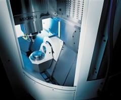
Figure 6: Direct drive rotary/tilt axes.
The direct drive rotary/tilt axes shown in Figure 6 can achieve speeds of 250 rpm and 150 rpm in the rotary and tilt axes with corresponding accelerations of 300 and 100 radians per second squared. With these values, the rotational axes can now match the feedrates and acceleration of the linear axes, thereby enabling true high-speed machining simultaneously in all five axes. Applications for this exciting technology are in turbomachinery parts and intricate molds and dies, as well as in the complex and challenging shapes required in medical part manufacturing.
Conclusion
Recently, there have been many interesting developments in high-speed machining technology. Behind the sleek enclosures of the new high-speed machining centers are stiffer improved structures that set new standards for high-speed machining performance while offering better ergonomics; smarter, more capable spindles; intelligent control systems; automation capabilities to keep the machines running around the clock; and an advancement of the process itself to true high-speed machining in all five axes for applications known and those yet to be discovered.
Related Content
The Benefits of Hand Scraping
Accuracy and flatness are two benefits of hand scraping that help improve machine loop stiffness, workpiece surface finish and component geometry.
Read MoreFundamentals of Designing the Optimal Cooling System
The right mold components can help improve mold cooling and thereby produce higher-quality parts.
Read MoreRevisiting Some Hot Runner Fundamentals
What exactly does a hot runner do? If you’ve been in the injection molding industry for any length of time, you might think the answer is obvious, but it is not.
Read MoreIt Starts With the Part: A Plastic Part Checklist Ensures Good Mold Design
All successful mold build projects start with examining the part to be molded to ensure it is moldable and will meet the customers' production objectives.
Read MoreRead Next
Making the Most of High-Speed Machining
High-speed machining can cut mold manufacturing time in half, but only if it’s executed with an eye to the special needs of the tools and the process.
Read MoreDefining What Makes High-Speed Machining Different
A look at what true high speed and true high precision can produce, as well as what makes high-speed machining different from traditional milling.
Read MoreHow to Machine Micron-Level Precision Molds in One Try
On-machine measurement intelligence and modification technology helps mold builders overcome machining variables and quickly produce micron-level tolerances.
Read More
