White-Light Scanning Validates Faster, Better Processes for Molded Auto Interior Trim at Eifel Inc.
The use of white-light scanning and photogrammetry ensures accuracy of tool building programs.
Eifel Inc. (Fraser, MI) uses white-light scanning and digitized inspection to validate the key steps in product development to production molds. The validation is part of Eifel’s Simultaneous Product Development and Manufacturing™ or SPDM, a unique concept-to-completion approach to designing, engineering, toolmaking and verification of plastic parts for the automakers and their Tier One suppliers.
“SPDM is the core of the business here,” explains Richard (“Rick”) Hecker, Eifel president. “Our design and manufacturing teams work in unison to produce superior results in a shorter amount of time with greater attention to cost and quality. We offer the upfront studio work, engineering and design and then manufacturing right to the final tools.”
This makes Eifel an extension of its customers’ design staffs and product engineering teams, while helping to boost sales, shorten delivery times and maintain profit margins.
Helping keep SPDM effective and keeping jobs on track is validation at every major step with white-light scanning (sometimes known as “structured” light) and photogrammetry. For these services Eifel relies on 3D Scan IT in the nearby Detroit suburb of Royal Oak.
“We use 3D Scan IT in studio work where designs are developed and refined,” notes Hecker. “The scanning process begins in the studio where we capture point cloud data from the clay model. We scan again at the end of the process, where we make sure customer specifications were met.”
In turn, 3D Scan IT relies on PolyWorks from InnovMetric Software Inc. (Quebec City, Canada) to sort out the millions of points each scan generates. PolyWorks aligns multiple overlapping scans, cleans up the data, edits it to a manageable file size, converts it to polygons, and then does curve fitting and feature fitting. PolyWorks also generates CAD data in the form of non-uniform rational B-spline (NURBS) surfaces, NURBS patches and polygons in the Stereolithography Tessellation Language (STL) format.
Eifel’s primary tooling niche is steering wheels—more than 60 of them in recent years—and driver side airbags that are mounted in steering wheel centers, or bezels. An Eifel customer, Vern Phillips of Autoliv North America, points out, “The 3D Scan IT inspections at Eifel reassure us that everything is going well dimensionally, so we can inform our customers as to the progress and the accuracy of their tool building programs.”
Phillips is a principal engineer for airbags and steering wheels for Autoliv North America, located in Auburn Hills, MI. The company is a Tier One automotive supplier of safety restraint systems. Autoliv’s global headquarters is located in Stockholm, Sweden.
SPDM and validation offer several benefits to Tier One customers like Autoliv. Phillips summarized them as:
- Being able to evaluate what’s happening with part shrinkage by comparing the final molded part to the master CAD model, thanks to the excellent information now available in the PolyWorks color map. Adds Hecker, “There is nothing like it for helping the customer visually understand the decision-making process.”
- Knowing that tooling will be absolutely correct in every other regard, thanks to closing all of the information loops with 100 percent surface inspection and verification to the math model.
- Maintaining a high level of credibility for Autoliv with its customers.
Savvy and very focused, Eifel handles many other automotive programs:
- Product development and tooling for exterior ground effects packages such as rocker panels that are added in a vehicle’s third or fourth model year.
- Developing class A surfaces for new interior options such as DVD player controls molded into headliners (ceilings) of minivans.
- Digital mockups for locating points in components as different as under-hood engine covers and driver seating.
SPDM at Eifel is nothing less than fully integrated and simultaneous design, engineering, tool manufacturing and final inspection of molded parts—the whole process from design intent and creation in the studio to completion. Validating the math model upfront, and then verifying that all the engineering and the machining conform to it ensures that Eifel is always working to the correct data. SPDM also maintains Eifel’s best practices, good process control, and high quality.
Good, quick comparative data also improves critical path planning. This helps ensure that costs are reliably estimated and jobs quoted precisely. Finally, SPDM allows Eifel to work concurrently rather than in a series of sequential steps. Eifel can’t afford to wait until the A-side or cavity of a molding tool is completed before starting on the tool’s core.1
In recent years, concurrency in design and engineering has allowed Eifel to reduce the product development cycle by 40 to 50 percent. “It all comes down to upfront engineering and design to perfect the final master CAD Model,” Hecker says.
Challenge: Eliminating Judgment Calls on Surfaces
SPDM and the validations that go with it address a fundamental business problem for moldmakers. As Hecker puts it, “When the mold shop is trying get part approval from their customer, it should not be based on someone’s visual interpretation but on the math data.”
Prior to the comprehensive surface measurement techniques of scanning and digitizing, subjective and even arbitrary judgments of surface quality were routine. They were often based on nothing more than a customer running a hand over a finished surface. Computerized inspections were touch-probed, one point at a time for a few hundred points. “That was fine for feature call-outs or locating points in 3-D space, but was far too little to verify that a surface conformed to the math model,” Hecker explains. “That left the moldmaker at a big disadvantage when disputes arose.”
Solution: More Complete Surface Inspection
For Eifel, the solution to these SPDM challenges is validation with white-light scanning and photogrammetry. They were chosen over laser scanning because white-light scanning is superior in collecting all features in the point cloud data.
Many advantages in visualization, surface development and data alignment arise from the differences between laser and white-light scanning. Instead of inspecting surfaces by laying down thousands of 3-D points along thousands of tiny scan lines, as lasers do, white light systems photograph the surface. Explains Bob Squier, president of 3D Scan IT, “Every pixel in a white-light image is a point in 3-D space. No part of a surface can go uninspected, as can happen between scan lines.”
In addition, white-light:
- Is simpler than laser systems since there is no need for a portable coordinate measuring machine (CMM), measuring arm or milling machine to maintain overall positioning while moving the scanner over the surface.
- Has far less “noise” (irrelevant 3-D points and data scatter) in its scans because there is no system movement whatever and thus no vibration.
- Has greater overall accuracy because in many cases there is no need to use multiple setups or “Leap Frogs” that can lead to a build-up error.
- Has a much larger field of focus, so less time is consumed in aligning multiple scans.
Both white-light and laser scanning need to be referenced to the car’s body coordinates. White-light scans are oriented to each other and to car-body coordinates with half-inch diameter round targets with black and white quadrants. This is photogrammetry. “The targets create something like a global positioning system, a GPS for the vehicle,” Hecker notes.
As examples, he offered a pair of mock-up projects to determine whether mounting holes were aligned with prepositioned bolts. Working in vehicle body-position coordinates, 3D Scan IT scanned:
- A front driver’s seat, IP and center console. Then they took the seat out, turned it over and scanned the mounting holes on the bottom of the seat track and the bolt locations.
- An entire vehicle engine compartment and its under-hood engine cover.
“This is not just capturing all of the data,” Hecker says, “but all of the data in the right position. In white light, you always know where the scan goes in car-body coordinates. White light gives me everything I need to start reverse engineering.”
With 3D Scan IT’s scanning and InnovMetric’s inspection software PolyWorks, a surface can be painted with a million to several million 3D points in a minute or so. That is less time than it would take to gather a few hundred points with touch-probing, which leaves more than 99 percent of the surface uninspected. “That’s why I sold my CMM,” Hecker says.
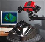
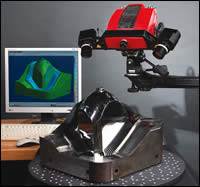
3D Scan IT uses a dual-camera Imetric-IScan White Light scanner ideally suited for inspection, reverse engineering, copy milling and tool archiving. Measurement volumes range from 75 millimeters (mm) on a side, or about 9 cubic inches, to 1,500 mm cubes or 180 cubic inches. IScan is accurate to 0.005 mm (5 microns or 0.0002 inch). Resolutions vary between 1.3 million, 5 million and 8 million XYZ points.
Acquisition time is 30 to 90 seconds per scan, depending on sensor resolution. Getting a good image requires several overlapping scans for small objects and several dozen for a vehicle body exterior or a large A-side mold cavity. Reflective and dark surfaces pose no problems.
InnovMetric’s IMetric photogrammetry software assembles the scans and positions them to body coordinates. PolyWorks polygonizes the completed scan and then surfaces the polygons for comparison to the math model. PolyWorks also creates NURBS surfaces and feature curves so scanned data can be added to math models.
“Addressing any issues upfront by inspecting finished tooling, before parts are molded, ensures that you’re not trying to chase your tail, that the mold is wrong in some way, or that there is a process issue which needs to be resolved,” says Squier. “Each step in the process is closed out with an affirmation of quality.”
Results: Validation Used Throughout SPDM
Scanning and digitizing play major up-front roles when new components are needed quickly. For example, when the DaimlerChrysler PT Cruiser needed a styling refresh, a ground effects package was created at Eifel. It included molded plastic trim at the bottoms of the rocker panels (below the doors), (front) fenders and (rear) quarter panels. Eifel designed and built the tooling and produced first parts in just 12 weeks instead of the usual 24 to 48 weeks.
The timeline was:
- Three days, scanning the automaker’s clay models.
- Two weeks, virtual sculpting to turn scans into surfaces, including studio review and buyoff.
- One week, finalizing B-side core tools; development was done simultaneously with the A-sides.
- Eight weeks, mold manufacturing; machining began as soon as parting lines were established and runoff surfaces were created.
The remainder was engineering analysis and decision making.
The results of validation with white-light scanning show up in key phases of SPDM, like in the studio phases of creating and sculpting parts. This is where the stylist’s creation is validated to car-body position and subassembly position. If it is clay, the new feature and the existing car surfaces are scanned and compared to the math data.
“The scans hold everything to assembly realities such as tolerance stack-ups and possible interferences with other components,” Hecker explains. “This goes beyond inspection. Without white light, nobody can capture the surfaces relative to their position on the vehicle. This gives us best fit and best practices, and catches any discrepancies.”
These results also appear in design engineering, where the stylist’s requirements meet engineering reality. This is nicely illustrated by textured surfaces that are deeply grained for a wood-like appearance. Such surfaces require draft angles of 3 to 8 degrees, depending on the depth of the grain. “If the proper draft angle is not incorporated in the surface, then this could lead to scuffing on the part,” said Hecker, “and that would be unacceptable for production.”
One of the biggest changes in recent years in automotive tooling is that visible outer surfaces—the A-sides of injection molded plastic components—are now precisely measurable. “That means moldmakers are now held accountable to the math data and that they need to minimize the hand benching on cavity surfaces,” Hecker points out.
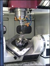
On the other hand, A-side measurability made net-shape machining2 practical for mold manufacturing; that is, cutting precisely to the math model’s surfaces. This has allowed Eifel reduce hand finishing and benching by 90 percent or more. “On a typical steering wheel program, benching used to take 30 to 40 hours,” Hecker notes. “Now that’s almost never more than five hours.
“A-side surface validations with point-cloud inspections let us know when we are there, right to the math model,” he adds. “And we can prove it. We have the data to check any point location the customer wants to see, and any surface.”
Benefits: Ensuring Business Transformation Stays on Track
Eifel transformed itself by moving to SPDM in 2003-04. “Scanning and digitizing help ensure SPDM stays on track. We reap the benefits in manufacturability and in maintaining margins,” Hecker says.
In summary, validation with white-light scanning and digitization:
- Offers absolute assurance that no surface flaw in the A-side tooling has been overlooked.
- Multiplies the time available to mold designers and engineers to think, react and make crucial tooling decisions.
- Provides a competitive edge over low-labor-rate moldmakers who often miss small but crucial details.
- Ensures that Eifel’s departments “perform project tasks concurrently with support from each other,” Hecker explains, “in a seamless process derived from design know-how and manufacturing expertise. Design feasibility issues and manufacturability problems are discovered and corrected earlier. Any need for later rework is eliminated.”
- Eliminates hand changes that do not get uploaded to the math model.
- Improves business relationships. “Now I can prove our surfaces are right on, and that there is nothing in the tool’s surfaces that was not supposed to be there,” Hecker says. “If there are disputes that gives me a lot of leverage.”
References
1 The core contains the mechanical components of the tool—lifters, slides, ejectors and other moving components that form attachments and other features of the part’s inner, non-visible B side.
2 Eifel’s machining is done mainly on three large, rigid vertical machining centers designed for moldmaking. They are a Johnford Hi-Net 1200 and two Topper QMC 1100s, all bought in 2003 or ’04. Each has a 12,000-RPM HSK-100 spindle and often runs at 120 inch-a-minute feed rates in roughing. Controlling the Johnford and the Toppers are Fujitsu-Fanuc Model 18iMB Nano CNCs capable of 5-micron accuracy. Combined with shrink-fit tool holders (for ultra-low run-out errors), these machines allow fast, light finishing cuts with small stepovers to generate high-quality surface finishes. This extreme precision eliminates cusps from machining, which is why so little benching is required.
Related Content
It Starts With the Part: A Plastic Part Checklist Ensures Good Mold Design
All successful mold build projects start with examining the part to be molded to ensure it is moldable and will meet the customers' production objectives.
Read MoreHow to Analyze and Optimize Cutting Conditions to Reduce Cycle Time
Plastic injection mold design and manufacturing company puts NC program optimization software module to the test. The results were surprising.
Read MoreHow to Fix Predicted Warpage Before It Happens with Windage and CAD Model Morphing
Applying windage and model-morphing techniques saved toolmaker/molder Sturgis Molded Products the time, cost, headaches of multiple part/mold design iteration loops, cumbersome cooling fixtures, and long molding cycles.
Read MoreWhat is Scientific Maintenance? Part 2
Part two of this three-part series explains specific data that toolrooms must collect, analyze and use to truly advance to a scientific maintenance culture where you can measure real data and drive decisions.
Read MoreRead Next
Taking Technology to New Heights
White light, non-contact scanning system adds new capabilities including real-time inspection.
Read MoreTransforming a Modeling Tool Into a Collaborative Environment
Simultaneous product development and manufacturing represents a breakthrough in design team interaction—streamlining mold design.
Read MoreChicago Mold Engineering: In The Spotlight
Focusing on a niche in the automotive headlap reflector market—coupled with the most advanced technologies and mold manufacturing techniques—lights the way for this moldmaker’s 2007 Leadtime Leader Award: Large Shop.
Read More
