Taking Technology to New Heights
White light, non-contact scanning system adds new capabilities including real-time inspection.
Chicago Mold Engineering’s (CME) high-tech mold manufacturing facility sets a high standard for speed and precision. Every machining center operator is well equipped with advanced five-axis CAM programming capability—and even the ability to update or revise part designs with CAD—right on the plant floor. Still, there are mold building processes and issues that arise which require electrode, steel or even part inspection or validation to ensure production quality throughout the mold build. Chicago Mold set out to find a means of gathering that data quickly and accurately.
White Light Scanning
Chicago Mold implemented the ATOS III white light, non-contact scanning system from GOM mbH U.S. distributor Capture 3D in 2004 after extensive investigation. With the ability to capture 4,000,000 points accurate to 0.001” in just 8 seconds, the ATOS III is both fast and accurate. Their research indicated that it would serve them well for both reverse engineering and for inspection.
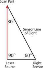
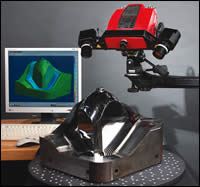
Consisting of a specialized stereo camera unit, a powerful computer, and sophisticated software, the ATOS III system is able to take several digital photographs of a part, and calculate surface data in a matter of hours for even the most complex parts. From the digital images, the computer quickly develops a mathematical model of the part.
Inspection
The ATOS III system complements Chicago Mold’s sophisticated CMM capabilities. Using the CMM is more precise, but unnecessarily precise in most cases—and it is tedious; often prohibitively slow. “Using the example of automotive headlight or taillight optics, we would normally take 10 points per optical facet,” says Jim Mazurek, Chicago Mold’s Inspection Specialist. Each of those points had to be programmed individually, and each point was then reported on individually in the CMM report. The process is inherently complex by its nature.
“Although it is not quite as accurate as our CMM, the ATOS III system more than makes up for that on most parts with its high speed,” reports Mazurek. “Digitizing 30 electrode pairs previously would have taken two weeks. Now we can do it in just hours. We end up with a lot more information about our part, so we have total confidence in its integrity.”
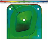
For inspection purposes, the reports that the ATOS III generates are dramatically easier to read as well. CMM inspections normally generate text reports or wireframe views of the part. The ATOS III can overlay the scanned part as well as the source data in a 3-D view, showing deviations from design specifications or from each other. The operator can instantly compare the final scan of the mold or part with its designed source file through colorized deviation maps set to show the required tolerances. Customers can look at that same picture and graphically see the quality CME builds into every mold.
Mazurek finds that one of the best features of the ATOS III system’s three-dimensional view is its non-static viewpoint capability. “The picture is completely interactive and clickable,” he notes. Instead of having several points from which to base a judgment, the operator can quickly see visually if there are any problems in a part. If there is any specific point that is in question, the operator can simply click at that location on the 3-D image. ATOS III can automatically create a report for that specific point on the part by triangulating between the other nearby measured points. With points in a mesh as close as .003", the interpolation is incredibly accurate.
Reverse Engineering
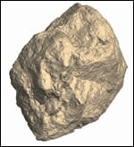
Chicago Mold Engineering has found that the fast scanning inherent to the ATOS III system is key to attracting reverse engineering customers, too. The ATOS III system has been used for a wide range of applications—from scanning natural textures like stone, to obsolete parts where no information was available, to new molds manufactured offshore, where mathematical design information isn’t available.
“We are constantly looking to our customers for new ideas and challenges,” says Mazurek. “The ATOS III white light scanning system can do anything.” Those claims are supported by impressive examples that were presented to CME in their search for the best system for their needs. They saw demonstrations ranging from the scanning of models for Hollywood, to the digitization of sensitive archaeological artifacts, to analyzing recovered parts from failed spacecraft. Using the ATOS III, they can even improve on a sample model, even highly contoured shapes or natural textures.
Molds for Replicating Natural Materials
One of Chicago Mold’s many diverse uses for the ATOS III is for various building materials for commercial and residential use. Molds are created to emulate stone, as in pump or electrical covers. Prior to the ATOS III system, Chicago Mold used an abrasion process to make electrodes to EDM the mold cavities. While that method worked, the end product did not look as real as the original samples. By the very nature of the abrading process, the end product lost details that give natural surfaces and textures their attractive appearance. “There just wasn’t enough detail,” says Mazurek.
In addition to the minimizing of detail, those molds required lengthy turnaround times. It would take about a week to prepare a master sample in order to begin the abrading process. Needless to say, costs were considerably higher using the abrading technique to produce the needed electrodes, at times by nearly 60 percent. The extra time it took for the abrading was another detrimental factor.
With the intuitive ATOS III workflow, Chicago Mold Engineering can go from source part to mold build completely in-house. “We can scan two pieces of natural material and have the math models ready to send to steel in just hours,” says Mazurek. “Our customers can’t keep up with our fast leadtime!”
Retouching
Another benefit of the system is the ability to digitally “retouch” the part model. If there is something the customer doesn’t like, it is easy to change and fit the design to the customer’s specifications. This plays a key role in replicating natural textures so that the end product is visually pleasing to the consumer. In one particular case, the customer’s specifications included the natural patterned portion of the part, as well as a CAD-designed “non-show” section for installation. It’s easy to create a hybrid part with both natural and man-made designs in one part.
Portability
Chicago Mold Engineering’s decision to purchase the ATOS III was based in part on the portability of the system, which included shipping cases to allow travel on airplanes. It recently showed its versatility at a nearby airport. The system was packed up and taken on-site to scan part of an airplane. The underside of the fuselage was scanned to ensure that the navigational antennae could be accurately fitted to the complex contours of the aircraft. The portability, quick setup, and accuracy of the ATOS III system all came together for a successful result in just hours.
On-site Mold Scanning
A useful application of the portable ATOS III is on-site scanning of molds in production. Chicago Mold was recently called on to scan a mold right in the press. The solution to a customer’s molding issue required creating a new fixture to hold an insert in a mold where no model or design data were available. Further, the mold was in production and running behind; minimal downtime was essential. Once Mazurek and his ATOS III were on-site, their customer stopped the press briefly. Mazurek set up the ATOS III system inside the molding press, eliminating the time-consuming removal and re-setup of the mold. Within one hour, the press was back to producing parts, and the ATOS III system was generating surface data for the insert fixture. The customer saved days of downtime in comparison with stopping production to ship the mold to CME for reverse engineering.
“Today’s global market provides another great opportunity for us,” says Mazurek. “We primarily provide services to molders. They have a growing number of tools that are undocumented for one reason or another. The tool may have been built offshore, or its source may be unknown. That doesn’t matter to us. We can have math data to repair or replace that tool within just hours.”
Troubleshooting and Optimization
“The ATOS III is great for troubleshooting and optimization, too,” continues Mazurek. When a mold is not working properly, Mazurek can take pictures of the mold, and within just hours, ATOS III shows where the deviations from the specifications are on the part. Mold performance can be optimized by measuring samples shot with different cycle times. The various parts are analyzed for warpage, shrinkage and sink, to find the best balance of performance and quality required. The space to archive physical parts would be prohibitive for most molders. The scanned files to archive sample shots only take virtual space, making it easy to keep records of the results through the sampling process. “ATOS III helps us build a better mold, and helps our customers run more efficiently and make better parts,” he says.
Improving an Old Process and Opening New Doors
Throughout its short time at CME, the ATOS III system has made an impression far beyond initial expectations. Although the company had anticipated an outstanding improvement in speed, they had far underestimated those benefits. Company CEO and visionary Ralph Oswald says that the ATOS III has helped improve on old processes and opened many new doors.
“With the positive changes that have occurred, I can’t wait for the next three to five years,” states Oswald. Future plans include implementing a second ATOS III system in one of their robotic work cells. Each electrode will be automatically checked for integrity between the graphite mill and the EDM. The speed and accuracy will make it easy to implement 100 percent inspection for higher quality, while actually decreasing the time to manufacture electrodes.
Chicago Mold Engineering uses the ATOS III system for customer work as well as providing scanning services for other mold manufacturers. With this technology adding to CME’s competitive advantage, they are better equipped to satisfy their customers’ desire for shorter leadtimes on parts with continually tighter tolerances.
Related Content
How to Analyze and Optimize Cutting Conditions to Reduce Cycle Time
Plastic injection mold design and manufacturing company puts NC program optimization software module to the test. The results were surprising.
Read MoreHow to Select a Mold Temperature Controller
White paper shares how cooling channel analysis, which collects maximum pressure drop, total flow rate and heat dissipation, eases the performance evaluation of mold temperature controllers.
Read MoreTips for Tackling Mold Design, Machining, Cutting Tool and Wear Challenges
Tips for tasks ranging from reducing risk in part design and taking advantage of five-axis machining to refining cutting tool performance and reducing wear with guiding and centering systems.
Read MoreTolerancing in Mold Design, Part 1: Understanding the Issues of Conventional Bilateral Tolerancing
Mold designers must understand the location, orientation and form limitations of conventional tolerancing before changing to another dimensioning system.
Read MoreRead Next
Developing Generalized RE Methodologies for Moldmaking
The use of contact scanning and laser scanning systems can aid moldmakers with reverse engineering due to their speed, accuracy and low cost.
Read MoreEngineering on the Edge
CAD/CAM software enhances reverse engineering in order to create machineable CAD geometry.
Read More
