Transforming a Modeling Tool Into a Collaborative Environment
Simultaneous product development and manufacturing represents a breakthrough in design team interaction—streamlining mold design.
Those of you who follow current events know the difficult economic environment that those in the tool and die business face in supplying the automotive industry. As automaker customers deal with global competition, technology advances and car buyer pricing pressures, automotive suppliers have to find every avenue available to lower costs, yet make their processes even more productive.
One way to meet increasing customer demands is the implementation of the simultaneous product development and manufacturing (SPDM™) process, as was done by Eifel, Inc. (Fraser, MI)— a leading Tier II automotive supplier that specializes in high technology CAD product design and development to final turnkey production tools for plastic interior and exterior parts. A confidence in this process has resulted in a significant reduction in mold build times, improved overall product quality and more cost-effective shop operations.
Technology and People
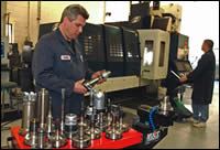
An indispensable part of implementing the SPDM process is a serious investment in the latest tooling and design technology. Eifel made the decision from the very beginning to rebuild its tooling and engineering business from the ground up—computer networks and servers, design engineering software and high-speed milling equipment that amounted to more than $3 million.
But even with the latest and most expensive technology resources and superior engineering processes, if you don't have the right people in place to make it all work together, you won't achieve the results that you expect.
For this reason, much of the initial efforts went into building strong cross-functional teams of CAD designers, engineers and toolmakers. After a highly structured, month-long training program, the technicians became thoroughly proficient in implementing the processes by using technology to its fullest extent. This regimen has produced a staff of highly skilled designers and engineers with between 15 and 20 years of individual experience.
In addition, a significant storehouse of past project technical data, notes and other information is readily available to employees as part of a lessons learned library. This repository can be used as a valuable data reference source for current and future projects, an institutional memory that keeps the technicians fully aware about previous solutions and approaches to similar issues.
SPDM Versus Traditional Processes
Part design and mold building processes traditionally have been two sequential and disconnected operations, requiring many serial design changes before approved product specifications are finalized.
In the past, part design parameters were discussed and developed with final customer approval needed before any mold design and fabrication was undertaken. Thus, by delaying the time when mold design could actually begin, precious hours and weeks are wasted while the overall design was being developed.
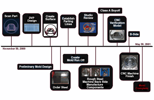
SPDM stands this method on its head by treating mold development as a concurrent process, overlapping part design and development at the same time. By making tooling a parallel process to part design, there is now an opportunity to dramatically drive down tooling fabrication times and costs, and also foster innovation with the added agility that has been gained.
Scanning and Design
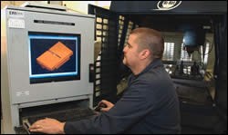
The initial design stage starts in the studio. The concept for a part is submitted as a sketch, reference data or in the form of a clay model, which is then optically scanned to produce a point cloud that is downloaded directly into ICEM Surf or CATIA CAD program. The point cloud can then be used to configure the desired shape and critical Class A surfaces. Any additional patches are mapped directly onto the scan cloud to best describe the part concept.
As various surface diagnostics are examined, reflection lines, curvature, shading, deviations from reference data and other characteristics can be gleaned using real-time analysis. Stylists are now able to transform their creative concepts into production-ready designs by means of freestyle sketching and shaping, robust surfacing, and powerful conceptual tools for visualization, animation and rendering.
Further, the built-in intelligence and flexibility of today's CAD software helps drastically reduce design steps by making it easier to understand a design and apply changes to it at any stage in the development process.
Shops can now produce unparalleled surface quality and mold accuracy, and allow the designers to configure production quality surfaces in a fraction of the time that other systems would require for the same task.
As the product design engineers optimize the Class A characteristics, the manufacturing team studies the design to review the implications for the part's Class B surfaces—an early step that will sidestep any complications in the tooling process.
The Tooling Phase
Once the tooling managers are confident that a tool can be built, the collected data is used to determine the appropriate process and begin their preliminary mold design—while the part surface is still being created. Since they have been involved in the part design process, they now have an accurate sense of the part's dimensions and features, and are able to suggest an initial mold design. They will design the mold with enough flexibility to accommodate any customer-requested changes that may arise during a design review.
This parallel activity is the heart of the SPDM process. While beginning this phase so early in the program might appear risky to some, the built-in anticipation of possible changes allows the process to work. Knowledge of the process is the key.
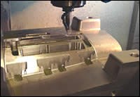
Parametrics design software—accessing a constantly updated database of variables—allows the user to predefine, plan and apply complete die and mold machining sequences through templates and process assistants. These sequential processes—such as determining mold flow, core and cavity machining, including Z-level roughing, semi-finishing, steep and non-steep area milling, uncut material removal, finishing and profiling—can be easily and quickly determined.
Once the mold design has been approved per the client's specifications, the steel mold materials are ordered—a cost-saving step that can be confidently made because of the collaboration between both the part design and tooling engineering teams. Next, when the parting lines of the part design have been established, the manufacturing team creates the mold run-off criteria.
With SPDM, any changes made to the virtual model can be instantly made directly to the design, allowing styling engineers to review the design changes for quick approval. All teams participate in the final design studio review, confirming attachment methods and approved specifications.
After the design review—and when the customer has signed off on the Class A surface— the approved data is transferred to the manufacturing design department for final verification and mold completion.
Bottom-Line Results
From start to finish, the SPDM process takes approximately half the time of a traditional design-to-mold operation. With the added capability of net shape machining, deadlines can be met that would have been impossible to achieve using traditional methods. Simply put, SPDM represents a breakthrough in design team interaction with a solution that transforms a modeling tool into a powerful collaborative environment. By supporting an innovative sharing and merging paradigm, it enables the initial homogeneous 3-D data to be effectively communicated across all operations—a most efficient solution that allows shops to offer customers the highest level of service and quality in a highly competitive marketplace
Related Content
MMT Chats: Solving Schedule and Capacity Challenges With ERP
For this MMT Chat, my guests hail from Omega Tool of Menomonee Falls, Wisconsin, who share their journey with using enterprise resource planning (ERP)—and their people—to solve their schedule and capacity load monitoring challenges.
Read MoreThe Critical Role of Management Representatives in ISO 9001
In ISO 9001 quality management systems, the Management Representative (MR) plays a crucial role. While the 2015 version of ISO 9001 no longer mandates this position, having a trusted management member serve as an MR remains vital for streamlining operations and maintaining quality standards.
Read MoreMold Design Review: The Complete Checklist
Gerardo (Jerry) Miranda III, former global tooling manager for Oakley sunglasses, reshares his complete mold design checklist, an essential part of the product time and cost-to-market process.
Read MoreTop 10 Topics to Cover During an ISO 9001 Manufacturing Audit
Take a look at this practical hands-on approach to conducting a quality audit.
Read MoreRead Next
Standardize Before You Automate
After standardization, automation will create the largest increase in profits that any one area can produce.
Read MoreHow to Use Strategic Planning Tools, Data to Manage the Human Side of Business
Q&A with Marion Wells, MMT EAB member and founder of Human Asset Management.
Read MoreHow to Use Continuing Education to Remain Competitive in Moldmaking
Continued training helps moldmakers make tooling decisions and properly use the latest cutting tool to efficiently machine high-quality molds.
Read More
