A chromatic position sensor measuring a contact lens mold. Photo Credit: Mitutoyo America Corp.
As any mold’s integrity is paramount to output quality and success, this is where measurement machines play a critical role. Shops use these machines to verify a mold’s accuracy or the finished product created by the mold. For example, the accuracy demanded by manufacturers of medical equipment and tools, such as gears, syringes, tubing and bands, requires the mold builder to check both the mold and the output. Certain measurement machines are ideal for quality checking a finished product like lumens and tubing, while others are more appropriate for measuring the mold itself.
Typically, a shop uses a coordinate measurement machine (CMM) with an attached laser or contact probe to inspect one half of the mold, paying particular attention to the surface where the two mold halves come together. The users also inspect the surface finish with the addition of a surface finish unit. Although vision machines and CMMs are the most commonly used, there are newer technologies for mold and mold output measurement.
1. Points From Focus—Camera-Created 3D Scans
One of these is points from focus (PFF) technology, which uses the camera from a vision machine to create a 3D scan of a part. PFF technology offer less expensive, faster measurement. Unlike a laser or sensor, this technology uses a camera to capture an image with no additional hardware from which the user creates a 3D scan.

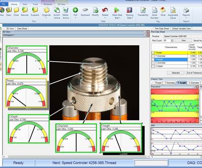
A measurement of a bone screw thread using points from focus technology.
The PFF technology is particularly useful when it comes to molding plastics. Concerns around the parting line’s size and the risk of flash can result in a mismatch in the alignment of the two molded halves. PFF can capture a good quality scan of the parting line, measuring its size and identifying any undesirable abnormalities. This technology is also useful for threads that screw a needle into a syringe because the user can conduct a scan that provides a closer look at the threaded contour.
Mold measurement is also an ideal application for PFF technology, which can be used to scan a mold for a high-resolution image of the mold’s features and contour. Seeing any potential flaws in creating a mold enables a user to fix a mold before creating parts, saving time and money.
2. Small-Diameter Probing Machine

A 125-micron contact scanning probe measuring a medical part.
A micro-scanning probe machine with accuracies down to 0.8 microns is another recent measurement technology. This type of vision measuring system uses a scanning probe with a ball diameter as small as 125 microns, making this technology ideal for inspecting parts with small features or contours. For example, a camera on a vision machine can scan a contact lens and its mold with high precision, but a microprobe can scan the mold surface for minuscule differences in surface contour that a camera could not measure. The same is true for plastic and metal gears in all applications, including medical. A microprobe permits a user to measure microform deviations in a mold and finished product. The camera provides perfect positioning for the probe’s placement while also making highly accurate overall measurements.
This probe process takes longer because vision measurements are nearly instant, while a probe must physically contact the part and scan. However, having a probe and vision measurement in the same machine saves time since both sensors are combined. The scanning probe does not have to rotate to take multiple measurements like on a CMM with a laser to provide the same contour and profile measurements.
Another benefit of a micro-scanning probe machine is how it handles shine compared to a laser. The probe touches what it measures, making optical interference a moot point, which is well suited for clear plastics, metal and other reflective surfaces.
Scanning with a chromatic position sensor or points from focus technology is contactless, while using a contact probe is contact scanning. Contactless scanning is preferred if scratching, defects or contamination are a concern. However, contactless scanning does not offer scanning flexibility due to the camera or sensor's fixed position.
3. Chromatic Position Sensor
A chromatic position sensor (CPS) can be used with a vision machine. It works by shining a white dot down on a part, which measures the Z height. For example, the chromatic position sensor scans across the surface of a contact lens mold at multiple points to make a 3D contour (point cloud) to which the user compares the CAD file to verify the correct contour or to simply output the scan data as a diameter without the need for a comparison.

A point cloud used to create a file from which you can measure a mold or molded product.
A point cloud is a collection of points used to create a file from which you can measure a mold or molded product and is highly versatile. For example, you can derive a point cloud from a PFF system, a chromatic position sensor or a scanning probe. You can also pair a point cloud with a heat map to indicate the location of scanned points, helping to confirm an accurate mold build.
Using a chromatic position sensor provides the flexibility of measuring a variety of part sizes up to the size that a particular vision machine can accommodate. This sensor will measure slower than a camera but can measure surface contours that a standard camera cannot, and do it with less than a micron in accuracy.
Advancements in vision measurement systems, such as camera technology and nanoprobe incorporation, provide multiple ways of measuring molds for plastics and finished products while using a single machine, which previously was not possible.
Related Content
Indiana Mold Builder Decatur Mold Offers a History of Grit and a Future of Innovation
Decatur Mold Tool and Engineering Inc. serves as a tooling tour guide, helping busy tooling managers reduce uncertainty, lighten workload.
Read MoreBreaking Down 3D Scanning in Moldmaking
Identifying 3D scanning requirements and implementing the appropriate technology.
Read MoreFour Micro Tooling Considerations
Issues involving gating, ejection, mold splits and direction of pull are of special concern when it comes to micro tooling.
Read MoreSoftware Strategy for Automated Mold Inspection
Consider inspection software with a CAD/CAM platform that supports model-based definition, works with all CAD files, and drives all fixed and portable CMMs.
Read MoreRead Next
Process and Measurement Data Aid Intelligent Moldmaking
Collecting and using measurement data ensures that mold components can meet customer specifications and reduces scrap and rework.
Read MoreImprove Overall Inspection with Automated Measurement
Automated shop floor inspection and measurement technologies are leading mold builders to smart manufacturing.
Read MoreHow to Use Continuing Education to Remain Competitive in Moldmaking
Continued training helps moldmakers make tooling decisions and properly use the latest cutting tool to efficiently machine high-quality molds.
Read More

