The Value of High Density Data
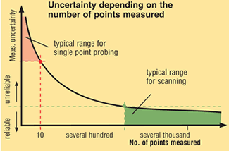
A minimum of 300 data points are required to approach the correct result for form.
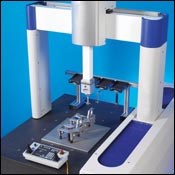
Coordinate measuring machines (CMMs) come in many types, but one important area of distinction is the method of data acquisition.
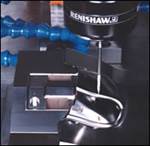
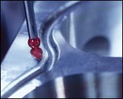
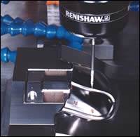
There are two basic methods: touch-trigger probing and scanning. Today, the touch-trigger CMM is the most common. It measures features by contacting individual points on the workpiece. The scanning probe CMM uses a probe sensor that is, by itself, a small measuring machine. Linked to the larger CMM with advanced control technology, it continuously scans the contour of the workpiece surface. Scanning CMMs can collect hundreds or even thousands of independent points to define a part feature in the same time it takes touch-trigger probe CMMs to measure only four to eight points.
When choosing a CMM, it’s common practice to obtain the machine’s measurement uncertainty from the manufacturer. The data are compared to part size and tolerances to determine the suitability of a particular CMM for a given application. There is, however, one potential shortcoming. Specifications for measurement uncertainty are made relative to traceable artifacts, such as gage blocks and ring gages.
One might ask, what’s wrong with that? It’s common practice to specify a system’s capability relative to known artifacts. But it must be understood that these known artifacts are produced to have nearly perfect form. They are actually gages, which are used to measure the CMM’s performance.
The fact that they have near-perfect form makes them a relatively easy target to measure using low data density. CMMs are not functional gages. They sample a workpiece and use mathematics to relate the sampled points to basic geometric elements, such as circles, lines, planes and cylinders. When the workpiece has nearly perfect form, the number and location of the sampled points becomes insignificant when calculating the result.
In day-to-day use, CMMs must inspect imperfectly formed features. This task is much more difficult than inspecting artifacts with near-perfect form, because on imperfectly formed features the result can vary significantly depending upon where the CMM samples the feature.
Most people are aware of the need for high data density when evaluating form, but there is less awareness of this need when evaluating location and size. It’s easy to assume that if a particular feature has no specific form requirement, data density is not an issue. But it is important, and especially so when form isn’t controlled separately. Form deviation exists in all measured features, only the magnitude of deviation varies. When form is not controlled separately through the use of a modifier such as circularity (roundness) of a bore, then the limits of size control the allowable form deviation.
Studies show that a minimum of 300 points are required to approach the correct result for form such as circularity of a diameter in the 25-70 mm range. Only above this level of data density will you begin to approach 90 percent or more of the correct form value. Any method that uses lots of data will see a more complete “picture” of the surface and gain a better understanding of the true high-to-low variation. Low data density most likely will miss this variation.
You may have heard the saying “form follows function.” Ad agencies often use it to describe a product with a very functional appearance. The inverse of this saying, “function follows form,” is true in metrology. You cannot know the functional size, orientation and location without a reliable understanding of the form of a feature.
When evaluating a CMM, consider the influence that form has on size and location. It can be greater than any error inherent in the CMM. Select a system and method that can accurately measure production parts, not just perfect artifacts. If the CMM must pass a gage repeatability and reproducibility (GR&R) study, high data density is the best defense when challenged to repeat readings on imperfectly formed elements.
High data density also provides better functional results that lead to fewer problems in assembly, lower warranty costs and improved overall feedback to production processes.
Related Content
The Ins and Outs of Hot Runner Temperature Control
A training checklist that explains the why and how of proper hot runner temperature control and system management.
Read MoreFour Micro Tooling Considerations
Issues involving gating, ejection, mold splits and direction of pull are of special concern when it comes to micro tooling.
Read MoreQuestions and Considerations Before Sending Your Mold Out for Service
Communication is essential for proper polishing, hot runner manifold cleaning, mold repair, laser engraving and laser welding services.
Read MoreHands-on Workshop Teaches Mold Maintenance Process
Intensive workshop teaches the process of mold maintenance to help put an end to the firefighting culture of many toolrooms.
Read MoreRead Next
Team Approach Is Key to Proper Inspection
Using a group rather than one person and changing the order of inspection is a win-win for this moldmaker—repeatable results with no rework.
Read MoreBringing Greater Process Control to Moldmaking
Advances in machine accuracy, on-machine probing technology and non-contact toolsetting provide powerful tools for automating and speeding mold machining.
Read MoreApplying Continual Process Improvement with the Right CMM/EDM Setup
Shifting coordinate-acquisition from EDM to CMM yields dramatic productivity gains.
Read More
