Optimized roughing shortens tool paths and cycle times dramatically. These benefits have piqued the interest of many moldmakers, but shops must understand that this machining strategy does not apply universally across all workpieces. So, shops must evaluate every application before applying optimized roughing.
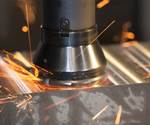
When roughing out a mold, moldmakers aim to produce a near-net shape in the shortest amount of time. Optimized roughing helps achieve that goal by using multi-flute tools with a cutting program that involves large depths of cut and shallow radial stepovers while maintaining a constant arc of contact (or angle of engagement).
Optimized roughing is the latest milling technique used in moldmaking, and at its core is traditional trochoidal milling. Optimized roughing is ideal for straight-walled cavities and other simple prismatic features. It is similar to slot-milling applications that first employed trochoidal tool paths.
A trochoid is a type of curve that is created by tracing a point on a circle’s radius as it rolls along a straight line. This movement is perfect for ensuring the constant arc of contact that enables the quick material removal approach used in trochoidal milling and optimized roughing. This movement also creates the perfect balance between speed, throughput and tool life consumption for many parts that were otherwise difficult or time-consuming to machine. However, this type of complex spindle movement along the X and Y axes is not possible without the aid of advanced CAM software.
Optimized roughing is ideal for straight-walled cavities and other simple prismatic features. It is similar to slot-milling applications that first employed trochoidal tool paths.
Optimal Uses
For moldmakers, the mold base itself is often the most promising application for optimized roughing, especially for applications involving a steel base holding heat-dissipating copper or brass features. The short stepovers and high depth of cut make it ideal for these and other similarly prismatic part features. For example, an end mill performing optimized roughing will cut these parts three to four times faster than a comparable high-feed mill while causing significantly less tool wear.
Those same stepovers, however, prevent the use of optimized roughing for complex 3D contours and surface features. Although in theory these types of parts may still be faster to rough out with optimized roughing, the moldmaker must consider the downstream effects. Optimized roughing will produce 3D surfaces with big stair steps as a result of the large depths of cut. So, even if optimized roughing is significantly faster than using another milling strategy, it will require additional semi-finishing passes to achieve a near-net shape.
Despite this, optimized roughing remains useful even for relatively complex features when it comes to material removal. For example, moldmakers often use high-speed machines that prevent the use of large high-feed milling cutters. Moldmakers would ideally rough out 3D surfaces using a large high-feed mill, but without the torque to achieve the necessary large stepover for this strategy, the tool would stall against the workpiece.
In other words, while optimized roughing may require more semi-finishing, it will still be appropriate when a moldmaker is starting from a solid block of metal or otherwise needs to remove a lot of material. It may not be the optimal approach for a given part, but it is still going to get shops closer to that near-net shape faster than conventional milling, especially when heavy roughing is not an available option.
Optimal Processes
For optimized roughing, shops should consult their cutting tool suppliers for optimized cutting data for any cutters that are designed specifically for optimized roughing. After a mold shop has determined if the part features are ideal for optimized roughing, it is time to consider the ability of the shop’s current equipment to perform the cutting program. As a relatively new approach to pocket milling, optimized roughing requires modern machine tools with the processing power and software support that is necessary to handle complex cutting programs.
The most important requirement is robust CAM software that has the ability to produce an optimized trochoidal tool path. Manually coding this motion is virtually impossible without the specialized algorithms included in newer CAM software. Some of today’s CAM software can generate an optimized roughing program simply by selecting that operation and assigning the tool definition, maximum stepover and pocket dimensions.
Optimized roughing also requires high-speed spindles, secure fixturing and a machine architecture designed for rigidity (or that is capable of holding 0.0004 of an inch or less tool runout necessary for optimal performance).
Optimized roughing is also hard on CNC controls. Trochoidal motions require many more lines of code than moving the spindle in a straight line. Only newer machines have the necessary processing power, given the speeds and feeds that are required to create that motion.
To fully understand optimized roughing, start with the part and the application, and then optimize from that point.
Even with the correct CAM software and machine, optimized roughing needs the right cutting tools. Typically, those tools are end mills with eccentric outer diameter reliefs and variable indexing to improve performance. The recommended feed rates and radial stepover for a given material dictate the number of flutes. Typically, end mills used for optimized roughing have between five and nine flutes. As a rule of thumb, fewer flutes allow for higher stepover, and more flutes enable aggressive feed rates.
Another rule to live by is ensuring the optimized roughing tool’s diameter is half its cutting length or depth of cut. Beyond that, axial cutting pressures on the tool will cause deflection and poor chip formation. Particularly deep axial cuts require chip splitters, which are notches in a cutter’s cutting edge that cause chips to break off before they cause problems.
For many moldmakers, optimized roughing represents the latest innovation in an industry that has seen rapid technological advancement. However, in a way that is similar to high-feed and high-speed cutting strategies, what may seem simple about optimized roughing has hidden complexities that can catch the unprepared moldmaker off guard. To fully understand optimized roughing, start with the part and the application, and then optimize from that point.
About the Contributor
Jay Ball is the product manager for solid endmills for Niagara Cutter LLC.
Related Content
Laser Welding Versus Micro Welding
The latest battle in finely detailed restoration/repair of mold materials.
Read MoreHow to Eliminate Chatter
Here are techniques commonly used to combat chatter and guidelines to establish a foundation for optimizing the moldmaking process.
Read MoreFundamentals of Designing the Optimal Cooling System
The right mold components can help improve mold cooling and thereby produce higher-quality parts.
Read MoreMoldmakers Deserve a Total Production Solution
Stability, spindle speed and software are essential consideration for your moldmaking machine tool.
Read MoreRead Next
Achieving Maximum Cutting Tool Life
Getting the most from cutting tools requires high performance from all elements of the entire cutting system.
Read MoreHow to Use Continuing Education to Remain Competitive in Moldmaking
Continued training helps moldmakers make tooling decisions and properly use the latest cutting tool to efficiently machine high-quality molds.
Read MoreReasons to Use Fiber Lasers for Mold Cleaning
Fiber lasers offer a simplicity, speed, control and portability, minimizing mold cleaning risks.
Read More



.png;maxWidth=300;quality=90)


.png;maxWidth=970;quality=90)