Developing Generalized RE Methodologies for Moldmaking
The use of contact scanning and laser scanning systems can aid moldmakers with reverse engineering due to their speed, accuracy and low cost.
Reverse engineering (RE), the process by which an existing item is identically reproduced, becomes necessary when a physical prototype exists, but an accurate geometric data file of the part does not. In order to recreate the existing part, a computerized (CAD) model of the part must be drawn or otherwise acquired. This CAD file provides the coordinates of multiple points on the product surface, which is then used to develop the drawing of the product for redesign or manufacturing. This data may then be analyzed within the CAD program or exported to a machine capable of rebuilding the new design or its tool, such as rapid prototyping (RP) or rapid tooling (RT) equipment. Although the automatic regeneration of the CAD model without the time-consuming use of CAD software is merely a single step in the RE process, it has become the focus of the RE community due to the ongoing pursuit to acquire more accurate 3-D data in a faster and less expensive manner.
Collecting accurate geometric data of any manufactured part is complicated by the numerous surface curvatures and odd shapes associated with manufactured products. Inaccurate data can be obtained using handheld devices such as calipers, but the time required to gather sufficient quantities of this data becomes extensive and the results become susceptible to inevitable human error. Until the advancement of automated RE technologies, acquiring substantial amounts of data with acceptable precision was nearly impossible.
The rapid advancement of computer technology has given rise to numerous automated RE methods that utilize a broad range of technologies to acquire data. These technologies provide extremely precise 3-D geometric information of nearly any item. Two of these technologies, contact scanning and laser scanning, have become increasingly popular in several manufacturing industries due to their speed, accuracy and relatively low cost.
Application to Moldmaking
Applications of RE in manufacturing are widespread. There are many instances in which an existing part or prototype requires reproduction, but lacks the computer data necessary to do so with accuracy and repeatability.
Often new products, such as those produced by artistry for example, do not start from a CAD model but rather a prototype is built first. In such a case, the measurements of the new prototype are acquired so that repeatable and accurate production may ensue. Similarly, design changes are often required to an existing product for which CAD data does not exist or when shop floor changes to the product have rendered the CAD data obsolete. Numerous additional applications of RE in manufacturing exist and include the design of large equipment whose measurements can not be taken using metrology, replacement of worn or broken parts for which CAD data is unavailable, and inspection of a produced part compared to its original CAD design.1
These various examples make aluminum or steel mold production a logical extension to RE applications. Without the need to develop CAD drawings, CNC toolpaths can be obtained much sooner, leading to swift production of very complex but accurate injection molding tools. Also, prompt replacement of broken or worn molds that lack satisfactory geometric data is facilitated considerably by advancements in RE capability. Essential geometric data for the broken tool can quickly be acquired by RE its product, leading directly to toolpath generation and rapid production of the replacement tool.
RE Technology
RE serves as a starting point in the product redesign process, during which the product is analyzed in terms of its functionality, physical principles, manufacturability and ease of assembly, for the purpose of fully understanding every detail of the product.2 However, to begin the RE sequence, accurate geometric data from the surface of the existing part must be obtained.
There are several methods that can be employed to collect surface data. These methods can be broadly classified into two categories: contact and noncontact methods.3 Contact methods, the more traditional manner of collecting data that has been utilized for several years, requires contact between the surface and a measuring device, usually a probe or stylus. Conversely, newer noncontact methods typically use light, or laser beams, as the main tool for deducing surface information.
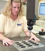
Contact methods of RE have been available for many years.4 The most popular method of RE has been the coordinate measuring machine (CMM). The CMM measures the surface of the object using a contact probe, a highly sensitive pressure-sensing device that is activated by any contact with an object. The linear distances from three axes to the position of the probe are ascertained, thus giving the x, y and z coordinates of the surface.
Although several alternative noncontact techniques exist, commercial methods have generally moved in the direction of laser scanning systems. These systems typically gather information by illuminating a point on the component and analyzing the reflected light beam. The location of the source gives the x and y coordinate measurements of the surface point while the analysis of the reflected beam by a triangulation procedure gives the third dimension.1
Contact Scanning
The best results in terms of accuracy and quality of surface finish are obtained using contact RE systems. Contact systems have several fundamental advantages over noncontact systems: treatment of surfaces to prevent reflections is not required, vertical faces can be accurately scanned, data density is not fixed and is automatically controlled by the shape of the component, time-consuming manual editing of the data to remove stray points is not required, postprocessing for cutting can be faster as surface offsetting may not be required, and very tiny detail can be accurately replicated.5
The contact systems' touch-trigger probes can be used to digitize components when fitted to either a CNC machine tool or coordinate measuring machine. Analog probes operate at very high scanning speeds, with excellent accuracy and low contact force. This allows better machine finishing of parts and the ability to scan relatively soft materials. The scanning probes have been developed for the intricate scanning of objects such as coins, watermark dies and jewelry, where fine detail requires the use of very low contact force.
Once the data has been captured, the scanning software packages are used to produce mold and die cavities, CAM profiles and templates. Model variants can be produced by mirroring, scaling, rotating, translating and inverting. Once the scan manipulation is complete, the software enables the user to manipulate data and then create a CNC program or export the data to any of several CAD output file types.
Laser Scanning
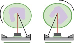
A rapidly emerging technology designed for accurate geometric data acquisition is laser scanning; these machines generally utilize structured lighting technologies. Laser scanners measure points on the part surface by computing the position of a laser spot projected onto the surface. The laser scanner casts a beam onto the object surface and then inspects the reflected beam using a sensor that is placed coaxial to the source. Mechanically, the laser scanning systems typically integrate both rotation of the scanned part and translation of the source (laser). They utilize geometric data acquisition methods that provide high-resolution measurements across the entire work volume (see Figure 1). These methods remove any need for additional mechanics to move toward or away from the part, thus removing any risk of destructive contact between the scanner and the part.6
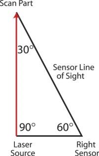
A common method of data acquisition is diagrammed in Figure 2. The view line of each sensor is fixed to thirty degrees relative to the laser beam. This creates a 30x-60x-90x right triangle between the source, sensor and part, the dimensions of which may be easily obtained with minimal information and simple geometric laws. To measure a surface point, the scanner rotates the object so that the point's surface normal is parallel to the laser beam. The laser beam and sensors are then translated horizontally to illuminate the point. Once the laser beam illuminates the desired spot on the piece, the sensors further translate until the view line of one of the sensors intersects the point. Thus, because the horizontal distance between the source and the sensor is known, and all three angles of the triangle are known, the depth measurement is easily obtained.
The four-axis capability of the laser scanner allows for the acquisition of complex, 3-D surface data in one scanning session without having to reset and rescan the part.6 Typically, laser scanning technologies are able to produce accurate geometric data repeatable to less than 0.001 in. and the data is highly compatible with most CAD software programs as well as rapid prototyping machines and CAM software.
Developing Laser Scanning Methodologies
Research has shown that strict RE methodologies may be devised for any classification of parts as opposed to a customized approach for each part (analogous to group technology manufacturing). Also, example methodologies for laser scanning illustrate that for every part family there exists an ideal manner in which parts may be scanned while avoiding potential trouble areas that may lead to poor scan quality or speed.5
For any product classification, several factors are expected to influence the scan quality and duration. Of these factors, three have been shown to be the vitally important parameters in obtaining high-quality laser scan data5:
1. Coating - the type of material used to coat the part for maximum reflectivity.
2. Horizontal point spacing - the horizontal distance between measured points.
3. Part orientation and mounting - the position of the piece during the scanning procedure and the manner in which it is held in this position.
Research results demonstrate credible evidence that the variability witnessed in scan quality is largely the result of the change in coating type, horizontal point spacing and part orientation/mounting. Further, changes in values of other variable parameters do not significantly affect the quality of the resultant scan data. In each experimental replication, substantial evidence suggested that the three aforementioned factors contribute most to the change in quality.5
Within these three factors deemed most important to the success of the scan, it is clear that a more dense point cloud - or smaller horizontal point spacing - produces a more accurate scan with fewer imperfections. However, the increase in density of the point cloud often leads to additional minor data editing tasks, which are easily solved using repair algorithms. Never does the increase in point cloud density lead to unsolvable data problems that would not have existed with a less dense data set. The converse is often true, however. Occasionally a low-density data set will exhibit data imperfections, such as a hole of missing points, that a high-density set will eliminate through its more defined search for data.
The single variable that most affects the quality of a scan is the part mounting and orientation.5 Any gains in quality seen as a result of optimizing the other variable settings can quickly be lost when improperly orienting the part. Furthermore, a subtle alteration of a part's orientation can lead to a substantial increase or decrease in scan quality. Often, in cases of oddly-shaped parts, a small number of orientation iterations can lead to a considerable improvement in quality.
Some observations for improving scan quality through part mounting and orientation are given below.5
- Whenever possible, the part should be mounted so that as little surface area as possible directly faces the rotation plate and the ceiling. Because the laser only moves in the X and Y directions, important geometries can be lost along the top and bottom faces of the part.
- For the same reason, concavities and holes should never be faced perpendicular to the laser source unless it has been determined that obtaining their geometric data is unnecessary.
- Often there is a specific region of interest along the geometry of the part. In these cases, ensure that the laser has an unobstructed sight line to all faces of this region of interest.
- If the geometry of a hole is a region of interest, ensure that the hole faces the laser at an angle between 30' and 45' from vertical. This enables the laser to have a direct line of sight to the interior faces of the hole and will minimize the loss of points. Note, however, that the internal geometries of holes are very difficult to obtain because the line of sight to one edge of the hole is often blocked by the other edge.
- If the geometry of a deep concavity is a region of interest, ensure that the hole directly faces the laser. This will give the laser a line of sight to gather any information it can from the deep concavity. Unfortunately, these obstructions are extremely difficult geometries to obtain and are often impossible.
- All mounting devices within the scan radius should be painted black whenever possible. The sensors of the laser scanner will be unable to collect point data at these locations.
- When using mounting devices, if the devices contact the part within the scan radius, ensure that the devices contact the part in locations where it will be easy to determine the location of missing points by simply observing several adjacent layers. For example, along the shaft of a long bone the geometry does not change a great deal from one layer to the next. In such cases, the resulting data holes can be filled easily through interpolation.
In general, the development of generalized scanning methodologies for part families can be successful. Clear evidence suggests that substantial improvement in scan quality can be obtained by utilizing the appropriate scanning parameter settings, and, more significantly, by orienting the item to maximize scanner efficiency. The traditional mentality, which suggests that scanning methods, and specifically orientations, should be determined on a case-by-case basis is inaccurate and unnecessary. Although some parts have notable obstacles that may require alterations to a scanning methodology, there is no question that most structures can be classified into part families that have similar, if not identical requirements for RE.
REFERENCES
1. Bidanda, B., S. Motavelli, and K. Harding, "Reverse Engineering: An Evaluation of Prospective Non-Contact Technologies and Applications in Manufacturing Systems," International Journal of Computer Aided Manufacturing, Vol. 4, No. 3, 1991, pg. 145-156.
2. Wood, Kristin L. and Kevin N. Otto, "A Reverse Engineering Design Methodology," http://madlab.me.utexas.edu/papers/reverse/reverse_1992/rev1.htm, Aug. 26, 2001.
3. Bidanda, Bopaya, Vivek Narayanan, and Richard Billo, Handbook of Design, Manufacturing, and Automation, Ch. 48, "Reverse Engineering and Rapid Prototyping," John Wiley & Sons, Inc., New York, 1994.
4. Bidanda, Bopaya and Yasser A. Hosni, "Reverse Engineering and Its Relevance to Industrial Engineering: A Critical Overview," Comput. Ind. Eng., Vol. 26, No. 2, 1994, pg. 343-348.
5. Creehan, Kevin, "Computer Aided Reverse Engineering of Human Tissues and Structures," Ph.D. Dissertation, Department of Industrial Engineering, College of Engineering, University of Pittsburgh, December 2001.
6. Digibotics, Inc., "Accurate and Automatic 3D Laser Digitizing Systems," http://www.digibotics.com, Oct. 14, 1999.
For more information contact Kevin Creehan of Virginia Tech Center for High Performance Manufacturing (Blacksburg, VA) via e-mail at kcreehan@vt.edu.
Related Content
Precision Meets Innovation at IMTS 2024
After attending IMTS, it's clear that the integration of advanced technologies is ready to enhance precision, efficiency and automation in mold manufacturing processes. It’s a massive event, so here’s a glimpse of what the MMT team experienced firsthand.
Read MoreHow to Manage Wall Thickness Changes in Your Mold Design
To ensure even filling and cooling, consider wall section transitions, corners and fillets, ribs and bosses, lip and rim designs and CAE flow simulation software.
Read MoreTolerancing in Mold Design, Part 1: Understanding the Issues of Conventional Bilateral Tolerancing
Mold designers must understand the location, orientation and form limitations of conventional tolerancing before changing to another dimensioning system.
Read MoreFour Micro Tooling Considerations
Issues involving gating, ejection, mold splits and direction of pull are of special concern when it comes to micro tooling.
Read MoreRead Next
A Better Reverse Engineering Approach when Modifying Molds
Laser scanning services make good economic sense as they provide precise CAD data available for robot programming, which shortens the actual programming process.
Read MoreReasons to Use Fiber Lasers for Mold Cleaning
Fiber lasers offer a simplicity, speed, control and portability, minimizing mold cleaning risks.
Read MoreHow to Use Continuing Education to Remain Competitive in Moldmaking
Continued training helps moldmakers make tooling decisions and properly use the latest cutting tool to efficiently machine high-quality molds.
Read More




.jpg;maxWidth=300;quality=90)


