Simplifying Mold Construction
How to solve your internal thread molding problems with the right core.
Plastic injection molding of internal threads presents some problems. In general, injection molding of internal surfaces—such as a medicine vial—is relatively easy. A slight draft on the cores’ surfaces allows the plastic vial to be stripped from the core by means of a stripper ring. The part slides off the core easily, the draft reduces the drag quickly and the soft part can be stripped without deformation. Even with shallow details on the core—such as engraved lettering and fill lines found on dosage cups or laundry detergent caps—the part can still be stripped by conventional means. When it comes to a threaded internal surface like a bottle cap a different method must be used.
Some threaded caps can be stripped. Changes are made to the flank angle of the thread, or the threads are relatively shallow. Certain plastics are easier to stretch over the threads and better at retaining the original molded shape after ejection from the mold. When the threads are deep and the material is not so flexible, the cap must be removed in a different way.
Rotating Core
Rotating cores are the most common solution to this problem. This is one of the most common setups. The rotating core features a gear, bearing journals and a retracting thread, in addition to the molding thread.
The basic operation is to rotate the core and retract it at the same time and at the same rate as the core is unscrewing from the cap on the other end. This requires several other components. Usually a rack is used to rotate the gear and an adjustable lead nut is used to time the retraction. The rack requires an air cylinder or some other means of drive. The core will require bearings of some type to allow free movement and guidance of the core during the retraction. The mold must have a feature to keep the cap from turning while the core is turning and retracting from inside. This is usually done with anti rotation lugs, which are cut into the ejection sleeve or into the stripper ring.
As you can see there are quite a few parts and some very critical timing involved in order to make a simple thread. It’s called a simple thread because the threads on a rotating core must also run all the way off the end of the core. If not the core would strip the threads off as it retracted from the cap.
Collapsible Core
The collapsible core offers some unique advantages to the traditional rotating core. The concept of the collapsible core is to first collapse the core to a small enough size to be able to clear all the molded features of the piece part, and then retract the core from the molded part. It sounds and looks a lot like a magic trick.
The basic core uses two components, an actuator pin and a collapsing sleeve. The sleeve is made up of several fingers of two types: (1) inner fingers and (2) outer fingers. The fingers are arranged in a cylindrical formation and all the fingers are bent toward the center of the cylinder. The inner fingers are narrower and bent further toward the center than the outers.
The actuator pin is a cylindrical shaft used to hold the fingers in place and to form the top section of the molding surface. When the actuator pin is inserted from the back of the core, the inner fingers are forced outward against the outer fingers. As the pin is further inserted, the inner and outer fingers move to their molding position and form a solid sleeve around the actuator pin.
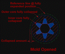
When you look at the core from the molding end of the assembly, the fingers look like pie sections placed next to each other in a circle around the pin. The way it works is that when the pin is removed the smaller (inner) pie sections will move to the area that was occupied by the pin. This produces gaps between the bigger (outer) pie sections. The outer sections move toward the center until the gaps are taken away (see Figure 1).
The actions all happen at the same time due to the spring loading of the fingers against the pin, and the corresponding angles on the flanks of the fingers allow them to slide against each other as the core is expanded or contracted. A tapered area inside the bore area of the sleeve allows the core to open at a controlled rate.
So a collapsible core has on average 12 fingers and a pin to form the inside section of a threaded cap. Each finger has three surfaces that need to seal out the plastic during the molding cycle. That’s 36 surfaces that need to come together within tenths! A pretty daunting task considering all of the fingers are bent to produce the spring action needed to close the core.
This brings us to the main drawbacks of collapsible cores. They may flash. Plastic moves into any gap that is large enough. The resulting flash can make the molded parts unacceptable. Plastic can build up on the flanks of the fingers and require cleaning. Spring pressures seem to be inconsistent. Current finishing processes use complicated fixtures and detailed instructions on how to finish the molding details without affecting the sealing abilities of the core. Some say that the cost of the core and its unreliable sealing ability and complicated finishing process make them a last resort.
Flash-Free Collapsible Core
The applications of a flash-free collapsible core are nothing short of incredible. Undercuts, O ring grooves, tabs, ribs, bosses, locking tabs, and threads are easily produced. Straight or even back-tapered bores are no problem.
Actually, all of the features listed could be combined on one core! Since the core contracts before the part is removed almost any feature can be molded into the side of a bore. No rotation is necessary.
Core Development
During the development of the core, the emphasis was on the sealing ability of the fingers as well as the simplification of the finishing process. Several prototypes were produced using three different manufacturing procedures.
A customer provided actual in mold testing at its facility and recorded the results. The first core flashed badly. A design flaw was discovered. Major design changes were made after this first attempt and a great deal of attention was put on the bending procedure. It seemed to be the key to a successful seal.
Two more prototypes and numerous changes to the bending fixture produced a working core. It was good, but it could be better. The best features of each of the prototypes were combined into a new design and three different processes were tried on three more prototypes.
To speed things up all three designs were run at the same time. A new and highly accurate bending fixture was created and used on all three. Initial testing in molding produced perfect results. More innovations and design changes made the core more robust and reliable.
The customer was very happy. Yet another larger core was produced using the latest design and submitted for testing. It performed flawlessly. As an afterthought it was asked if the core could be sampled using nylon instead of the intended polypropylene. The customer agreed and once again the core succeeded. The nylon was molded at 1800 psi with no flash. The core was produced using the standard procedure. It was not tweaked to run nylon; it just seals that well.
The current design had some interesting advantages. The entire core assembly is much shorter than previous designs. This allows it to be used in smaller presses, presses that could not support a rotating setup. It simplified the mold construction—no racks, no gears, no drive components that a rotating setup uses. All of the motions needed are performed by the normal open and close motion of the press. The finishing of the molding area has been greatly simplified. No special fixtures, no long instructions, just grind it! This presents a potential cost-effective alternative to a rotating core setup.
Summary
A look at your core setup options shows that when it comes to a threaded internal surface using a collapsible flash-free core will save time and money.
Footnote:
A patent is pending on the Hommer Tool collapsible core design.
Related Content
How to Eliminate Chatter
Here are techniques commonly used to combat chatter and guidelines to establish a foundation for optimizing the moldmaking process.
Read MoreMoldmakers Deserve a Total Production Solution
Stability, spindle speed and software are essential consideration for your moldmaking machine tool.
Read MoreLaser Welding Versus Micro Welding
The latest battle in finely detailed restoration/repair of mold materials.
Read MoreTreatment and Disposal of Used Metalworking Fluids
With greater emphasis on fluid longevity and fluid recycling, it is important to remember that water-based metalworking fluids are “consumable” and have a finite life.
Read MoreRead Next
The Advantages of New Modular Tech: Maximizing ROI and Minimizing Risk
Proven off-the-shelf modular mold components and complete component systems meet today’s demanding drive for a lean approach.
Read MoreMold Side-Actions: How, Why and When They Work
Understanding the effects of injection on the core, slide and associated components is critical to selecting the best side-action methods for a given application. This first of two articles will discuss the basic physics underlying all side-actions.
Read MoreUnscrewing Core Design Provides Fast, Accurate Core Positioning
Although PERC (Programmable Electric Rotating Cores System) is not a brand-new technology, it warrants a second look as a way for moldmakers to provide another value-added service to their customers.
Read More
