Rough Milling: Speed vs. Power
A look at what works in rough milling applications with solid carbide end mills.
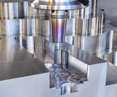
Focus on cutting parameters and tool path to optimize metal removal rates on a low-power, high-speed milling machine.
Oftentimes, we get so caught up in the hype about something new that we lose sight of the value of what already exists and truly works. This is especially true in the recent fad of using solid carbide end mills for high-speed milling in rough milling applications. Instead of presenting what’s “new” in cutting tool technology for mold manufacturers, let’s take a look at what already “works.”
The moldmaking community is no stranger to high-speed milling using solid carbide end mills. It’s been nearly two decades since the most adventurous and technology-driven moldmakers started using high-speed, hard-milling techniques for core and cavity finishing applications (mostly using ball mills). Many moldmakers started investing in high-speed milling machines that had spindles capable of 20,000 rpm (or higher) with the intention of using these machines only for finishing operations. Roughing operations would be performed on another, better-suited milling machine (one with more power, for example) and before the material was hardened/stress-relieved.
This approach of roughing on one machine and finishing on another is a solid process, but it still begs the question: “Can we rough and finish on the same high-speed machine?” The simple answer is yes. However, to be productive in terms of metal removal during the roughing phase requires a different approach.
Optimizing Metal Removal
To optimize metal removal rates on a low-power, high-speed milling machine, emphasis needs to be placed on the cut parameters and tool path to be used. Sometimes the cutting tool will be entirely different and designed to take advantage of the cutting strategy and/or material being machined.
Cut parameters. Radical adjustments of speed, feed, and depth and width of cut are all necessary considerations for optimizing high-speed roughing. With this approach, the radial engagement of the cutting tool is limited, so speed can be increased (often to the maximum spindle speed). It’s not uncommon to use spindle speeds ranging from two to five times the normal operating speed for a given material. In many cases, spindle speed is limited by the overall feed rate that the machine can keep up with. Milling machines, for example, accelerate and decelerate the feed rate to ensure accuracy and/or to optimize rough milling operations. It’s possible to reach a point where the machine tool will not feed any faster and will not achieve the programmed feed rate. If this occurs, the chips being generated will not be thick enough to carry heat away from the cutting zone. Then temperatures in the cut will be higher, and tool life will be negatively affected.
To accommodate for the light radial engagements being applied, feed rates must be adjusted. This adjustment is due to radial chip thinning (RCT), and it occurs anytime less than 50 percent of the tool’s diameter is engaged. The feed rate should be increased to achieve the recommended chip thickness, or tool life will decrease. (If you operate CNC machinery and are not familiar with RCT, an Internet search on the subject can get you moving in the right direction.)
For high-speed roughing, width of cut is usually set at somewhere between 5 and 10 percent of the cutting tool diameter. This means a 0.50-inch end mill will be engaged 0.025 to 0.050 inch. This setting will impact RCT calculations as well. For example, the average recommended feed rate for a 0.50-inch tool is approximately 0.002 inch per tooth. For a 0.50-inch tool operating at 0.025-inch width of cut, the feed would need to be programmed at 0.0046 inch per tooth to accommodate for RCT. RCT has a great impact on productivity when such small radial engagements are used. In this example, the tool would be operating 56 percent slower than it should be, and tool life would most likely be negatively affected.
If workpiece geometry allows, depth of cut should be set to the maximum possible depth (flute length) of the cutting tool (up to 3×D end mills). Light depths of cut using this approach would result in very low metal removal rates and poor utilization of the solid carbide end mill.
CAM tool paths. Many CAM systems have developed tool paths that enable precise control of tool motion. Simply put, the tool path maintains constant control on the radial engagement of the cutting tool, and this allows the cutting parameters to be increased to the highest possible level (usually limited by what the machine tool and/or workpiece will allow) without incurring a catastrophic cutting tool failure. It is very challenging to consistently apply the high-speed approach to roughing without access to modern CAM tool paths that control engagement.
An additional consideration for optimizing high-speed roughing are CAM systems with functionality to ease necessary calculations, such as CAM software that includes a slider bar that dynamically populates speed and feed adjustments for a given width of cut. All the math is performed by the software, so programmers can quickly and easily get a machine up and running in an aggressive manner.
Analyzing the Approach: Speed vs. Power
High-speed milling is fun to watch. When seeing a machine travel this fast (500 inches per minute or faster), it’s easy to become enamored with, and overuse, the approach. However, the vast majority of rough milling applications with solid carbide end mills are more productive when modern programming is combined with conventional cutting parameters (large widths and depths of cut). Think of this conventional approach as a “power approach.”
The same end mill that one would use for a conventional power approach can be used productively for most high-speed roughing applications. There is a tendency to use end mills with five or more flutes for high-speed roughing, but operators should beware: If the machine is not reaching the programmed feed rate, the additional flutes will have a negative impact on tool life. Workpiece geometry plays a big role as well. As geometry gets smaller/tighter, the aforementioned acceleration and deceleration functionality may prevent the machine from reaching programmed feed rates.
The conventional, high-depth-and-width-of-cut approach to applying solid carbide end mills is nothing new. What is new is the composition and design of solid carbide end mills, and the CAM tool paths that are driving them. As mentioned previously, solid carbide end mills used for the power approach will, for the most part, be of the same designs that would be used for the high-speed approach. The one big difference is that they will always be four-flute end mills.
The same CAM tool paths that are applied for the high-speed approach to roughing should be employed in the power approach. These tool paths are vastly underutilized for more conventional rough milling strategies. The same control of radial engagement that allows us to execute a high-speed approach gives us the opportunity to be more aggressive in the more conventional power approach. It’s not uncommon for cutting parameters to be nearly double what they were just a few years ago, even when milling the most complex geometry.
Cutting parameters can be set as if the tool is machining in a straight line, without worry about variations in chip thickness that result from old-style tool paths. In the past, cutting parameters had to be reduced to accommodate for unexpected tool motion that might bury the tool, spike the chip load and, most likely, break the cutting tool. This reduction caused a lot of vibration. As a result, more manufacturers chose to use the high-speed machining approach. Here, it was easier to find a stable machining zone (reduce vibration) and limit catastrophic tool failures. However, easy is not necessarily productive.
Since newer CAM tool paths eliminate unexpected tool motion, cutting tool utilization and metal removal can be maximized by fully engaging the solid carbide end mill. It’s typical for depth of cut to be set at 2×D (full flute length for most standard designs) and, in order for maximum performance to be achieved, for width of cut to be set between 60 and 80 percent of the cutting tool diameter. Operating at these parameters quickly reveals the quality of the solid carbide end mills being used.
Making a Decision
Material removal rate (MRR) is the main factor for determining whether to use the high-speed or power approach to roughing. A quick and simple method for close estimation is to multiply the width of cut by the depth of cut by the feed rate (inches per minute). This formula for MRR will involve a small amount of error, as it is a linear calculation that does not account for all the motion/acceleration and deceleration of the machine tool during an operation. The larger the tool path, the more deviation there will be from the calculation, particularly with the high-speed approach, since it involves more toolpath motion.
The tool paths discussed here involve a lot of motion, moving in and out of the cut multiple times to maintain controlled engagement. This means there is some air time between each pass. The larger the tool path, the more this “air factor” can skew the material removal estimations. Again, the air factor will be greater in the high-speed approach, because it involves more toolpath motion. Most CAM systems have controls to help minimize the air factor, but this also will skew metal removal calculations. All these factors should be kept in mind when using MRR to help choose between the high-speed vs. the power approach to roughing.
A final important factor in the decision is rigidity. It is advisable to consider if any of the variety of manufacturing technologies used in the roughing process (machine tool, cutting tool assembly, fixtures, machine tool attachments like angular heads) pose a rigidity issue. The recommendation would be to use the power approach for rigid scenarios and the speed approach for non-rigid scenarios.
Regardless of the roughing approach best-suited to your environment, you will most likely need to change how you’re programming and the cutting tools you are using in order to achieve optimal results.
Related Content
Revisiting Some Hot Runner Fundamentals
What exactly does a hot runner do? If you’ve been in the injection molding industry for any length of time, you might think the answer is obvious, but it is not.
Read More6 Ways to Optimize High-Feed Milling
High-feed milling can significantly outweigh potential reliability challenges. Consider these six strategies in order to make high-feed milling successful for your business.
Read MoreHow to Eliminate Chatter
Here are techniques commonly used to combat chatter and guidelines to establish a foundation for optimizing the moldmaking process.
Read MoreSolving Mold Alignment Problems with the Right Alignment Lock
Correct alignment lock selection can reduce maintenance costs and molding downtime, as well as increase part quality over the mold’s entire life.
Read MoreRead Next
Choosing Between Solid Carbide and Indexable Cutting Tools
Criteria like machine tool spindle power, workpiece geometry and material, CAD/CAM for CNC programming and fixturing drive rough milling cutter selection.
Read MoreCreating a Balanced Cut
Decrease machine downtime and increase productivity with the right gundrilling tool.
Read MoreReasons to Use Fiber Lasers for Mold Cleaning
Fiber lasers offer a simplicity, speed, control and portability, minimizing mold cleaning risks.
Read More




.png;maxWidth=300;quality=90)


