Choosing Between Solid Carbide and Indexable Cutting Tools
Criteria like machine tool spindle power, workpiece geometry and material, CAD/CAM for CNC programming and fixturing drive rough milling cutter selection.
What factors drive machinists to choose between solid carbide and indexable cutting tools?
Machine Tool. Most milling machine tools purchased in the United States today are lighter-duty machines with CAT40 or HSK 63 spindles, which generate low horsepower and torque when they are operated at slow spindle speeds. Price is one of the main purchasing criteria for buying machines with these light-duty spindles. However, in moldmaking the trend toward finishing cores and cavities in a hardened state over producing electrodes and using EDM to complete a workpiece has driven mold shops to invest in light-duty machining centers with high-speed spindles.
Programming. Advancements in CAM systems also are driving the selection of solid carbide cutting tools over indexable cutting tools. The ability to effectively maintain control of cutting tool engagement (or the width of cut) has provided the opportunity to optimize and maximize roughing applications, especially those involving light-duty, high-speed milling machines. These new algorithms can control the engagement of the cutting tool throughout an entire operation, no matter how complex the workpiece geometry. Without these algorithms, catastrophic cutting tool failures would result that could damage the part or the machine spindle over time. This is especially true on a high-speed milling machine since high-speed spindle design does not hold up well against excessive abuse.
Workpiece Geometry and Material. It goes without saying that workpiece geometry plays a major role in determining cutting tool type and size. However, workpiece geometry alone should not be the deciding factor for selecting a cutting tool diameter. For example, a given workpiece geometry may provide access for a 2.00-inch diameter cutting tool or larger. But, can a lighter-duty spindle be effective in running this cutter? A very common mistake in milling is to choose a cutting tool that is too large for a given machine to effectively operate. Machinists are forced to sacrifice the effective and efficient use of carbide by limiting the depth or width of cut when choosing a cutter diameter that is too large. It is critical to match the cutting-tool diameter to the machine tool capability while staying within the limits of what the cutting tool can handle in terms of speed in a given material. Using solid carbide end mills in a high-speed approach offers more freedom when matching the cutting tool to the machine and material, especially on light-duty machines.
Fixture and Part Clamping. Rigidity is the most important variable in machining. When rigidity is lacking, a high-speed approach that reduces force may be the only option for productive milling. For example, rigidity is lacking when the workpiece geometry makes it difficult to clamp the part, when holding onto a slim piece of material in a vice or when milling operations distort the workpiece with thin walls or ribs.
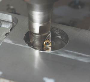
Milling Cutter Advancements. Most one-inch diameter and smaller cutting tools used in milling, whether indexable or solid carbide, are designed with two, three and four flutes. The design of indexable tools usually limits the addition of more flutes since a significant area is required to create the insert pocket and chip gullet. And, solid carbide tools with two, three and four flutes are still the most common due to their versatility. However, solid carbide and interchangeable solid carbide end mill designs are quickly evolving to optimize this high-speed milling approach. The small or light width of cut used allows the end mill’s chip gullets to be smaller, which provides the opportunity to add more flutes with longer lengths of cut.
Taking the machine, the material and the programming into consideration, the use of solid carbide cutting tools in a high-speed approach may offer more freedom to adapt to common machining variables and to match or surpass what has previously been done with indexable tooling. This is especially appropriate in a light-duty environment that lacks rigidity and where working at lower speeds would constrain spindle power.
About the Contributor
Tom Raun is national milling product manager for Iscar Metals.
Related Content
Treatment and Disposal of Used Metalworking Fluids
With greater emphasis on fluid longevity and fluid recycling, it is important to remember that water-based metalworking fluids are “consumable” and have a finite life.
Read MoreSolving Mold Alignment Problems with the Right Alignment Lock
Correct alignment lock selection can reduce maintenance costs and molding downtime, as well as increase part quality over the mold’s entire life.
Read MoreMachine Hammer Peening Automates Mold Polishing
A polishing automation solution eliminates hand work, accelerates milling operations and controls surface geometries.
Read More6 Ways to Optimize High-Feed Milling
High-feed milling can significantly outweigh potential reliability challenges. Consider these six strategies in order to make high-feed milling successful for your business.
Read MoreRead Next
How to Advance Molding Undercuts with Collapsible Core Design
A new flush-style collapsible core design might help to overcome objections to using the technology and advance the molding of undercuts.
Read MoreHow to Use Continuing Education to Remain Competitive in Moldmaking
Continued training helps moldmakers make tooling decisions and properly use the latest cutting tool to efficiently machine high-quality molds.
Read MoreHow to Use Strategic Planning Tools, Data to Manage the Human Side of Business
Q&A with Marion Wells, MMT EAB member and founder of Human Asset Management.
Read More


.png;maxWidth=300;quality=90)

