Maintaining Mold Components
Toolroom technicians must include frame plates, frame components, and cavity tooling when developing a mold maintenance plan.
The typical injection mold comprises hundreds of types of plates and tooling components that help to form and eject a molded part. Component type, required function, and construction dictate the proper maintenance procedure and frequency plan. To help toolroom technicians better understand the time and money they are spending on mold component maintenance, we have classified mold components into three categories: frame plates, frame components, and cavity tooling.
Frame or base plates include only the individual mold plates, which can range from seven plates in a simple stripper plate mold to 20 or more, depending upon mold size and complexity. Frame components include all tooling that is within the frame that does not form the part. For example, guide or leader pins, bushings, return pins, interlocks, bolts, and seals. Ejector pins are often also placed in this category. Cavity tooling is the most critical and expensive tooling in a mold because it includes the cavities, cores, sleeves, and pins that directly form the part. Cavity components dictate dimensional and aesthetic part features, so they are costly to build and replace.
A toolroom should view a report that breaks down mold maintenance and repair costs according to these three categories to identify mold problem areas and to track component maintenance correctly. A good rule of thumb is to base the severity of a problem area on maintenance cost (tooling and labor) per hour of production, or in some cases per 100,000 cycles of run time. This information helps to create accurate maintenance PM frequencies and build better molds.
Proper mold-component maintenance depends on a toolroom’s ability to recognize when and how a specific component needs attention. Every mold ever built, or that ever will be built, has a weakness. The design, build or production process can cause this weakness, which results in mold function or part quality issues if the toolroom leaves a mold unattended for a specific amount of run cycles. It is the tool shop’s responsibility to have procedures in place to recognize the cycle count at which a certain component requires specific attention. If a toolroom understands a mold’s performance characteristics and the conditions that wear out certain mold components, it can prevent these problems and greatly reduce breakdowns and quality issues.
Component design many times controls PM frequency. For example, if a component is moving (dynamic) then frictional wear becomes a huge factor in component longevity. Also, if a component is fixed (static), it can experience corrosion through water, off-gassing, condensation, abrasive resins, plate-out, and hobbing from clamp pressure on preloaded components.
Proper mold-component maintenance depends on a toolroom’s ability to recognize when and how a specific component needs attention.
Design, Build, Run
Let’s review some mold characteristics that cause premature component wear or breakage. (These are not listed in order as specific molding environmental conditions affect mold components at different levels.)
A molded part’s physical features, resin type, and required volume dictate mold design and build quality. Molds are graded. SPI 101-classified molds are at the top of the class. Any molds classified less than 101 avoid certain design and build features to reduce mold cost, which can greatly influence component life when the shop runs the mold beyond the specified cycle count.
Regardless of mold grade, the molding process will subject many dynamic or static mold components to excessive wear and breakage depending on tolerance levels (too tight or too loose), steel quality, and hardness. Steel hardness between dynamic tooling that varies by more than two points can cause premature wear or galling, assuming that the toolroom is performing timely PMs. Cheaply-made mold components of substandard, soft steels and poorly-designed mold components with excessive pre-load will wear prematurely even with regular maintenance.
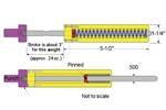
Other molding conditions such as how the shop sets up and runs the mold can be the root cause of many mold component issues. Molds bolted in improperly, platens out of square, hard mold closings, over-stroking mold openings, leaving heaters on during a shut-down, and a lack of proper grease during long runs are just a few of the issues that shorten component life.
Regardless of mold grade, the molding process will subject many dynamic or static mold components to excessive wear and breakage depending on tolerance levels (too tight or too loose), steel quality, and hardness.
Handling
The way a repair technician handles a mold can be harder on component life than the actual running of the mold. Often, a repair tech disassembling and cleaning a mold using too much force with the wrong tools or too coarse or abrasive cleaning methods will mix up, ding or scuff mold components. One common myth in some toolrooms is that the tech can get away with excessive force during component removal and installation if they use brass, copper and aluminum tools because they are soft. This is not always true as they can still round over and crack sharp edges, and create burrs that will eventually cause galling and excessive wear. As soft as brass, copper, and aluminum are, they will still chip and flake. These small slivers will fall into the wrong places during assembly and cause out-of-stack component issues, binding and galling.
Repair technicians must pay attention to the type of tool and the amount of force they apply when removing or installing components. Techs must correctly size punches on sleeves and pins with appropriate clearance to avoid jamming, dinging or rounding critical edges. They must also clean up the faces of a punch and remove the mushroomed head that forms after months of use.
Once a tech removes the mold components, they should not haphazardly toss them into cleaning baskets and swish or agitate them in solvent tanks, as this causes small dings and burrs. They should also not clean components with coarse scouring pads, sandpaper or stones, or use a sandblaster with glass beads, walnut shells or aluminum oxide. We recommend soft, plastic media, along with ultrasonics and dry ice. Techs should place delicate cavity tooling on a plastic rack to prevent them from banging into each other.
There are many available sources with opinions on how to build molds, many of which are steeped in personal experience. Others are not, and it shows up in the quality and performance of the mold that shop builds. Providing accurate feedback to these sources so the information can be used to help design and build better tools is an important part of a toolroom maintenance program. Technology for designing and building molds continuously advances, but it will never replace accurately documented mold performance hindsight.
For More Information
MoldTrax / moldtrax.com / 419-281-0790 / steve@moldtrax.com
About the Contributor
Steve Johnson
Steve Johnson is president of MoldTrax, which provides specialized course work, hands-on bench training, maintenance software, maintenance products, toolroom design and maintenance efficiency auditing.
Related Content
The Ins and Outs of Hot Runner Temperature Control
A training checklist that explains the why and how of proper hot runner temperature control and system management.
Read MoreLaser Welding Versus Micro Welding
The latest battle in finely detailed restoration/repair of mold materials.
Read MoreMold Design Review: The Complete Checklist
Gerardo (Jerry) Miranda III, former global tooling manager for Oakley sunglasses, reshares his complete mold design checklist, an essential part of the product time and cost-to-market process.
Read MoreRevisiting Some Hot Runner Fundamentals
What exactly does a hot runner do? If you’ve been in the injection molding industry for any length of time, you might think the answer is obvious, but it is not.
Read MoreRead Next
Across the Bench: One-Man Solution
A tool specifically designed to make tooling removal a quick, safe, one-person job helps moldmakers get jobs done quickly and efficiently.
Read MoreAre You a Moldmaker Considering 3D Printing? Consider the 3D Printing Workshop at NPE2024
Presentations will cover 3D printing for mold tooling, material innovation, product development, bridge production and full-scale, high-volume additive manufacturing.
Read MoreReasons to Use Fiber Lasers for Mold Cleaning
Fiber lasers offer a simplicity, speed, control and portability, minimizing mold cleaning risks.
Read More
