Improve Input Quality with the Right Tool Inspection and Monitoring System
Integrating efficient tool inspection before and after the cut with optimized tool performance in the cut improves mold manufacture’s efficiency and profitability.
There is a maxim in the computer industry known as GIGO, which is an acronym for Garbage In Garbage Out. It simply means that if one does not provide quality inputs to a process, one will not get quality outputs from that process.
The GIGO law also applies to moldmaking where the inputs are power and tools, and the output is either a usable mold or a chunk of expensive scrap metal depending on how well the inputs perform. Since the process is performed on the machine tool, it makes perfect sense to measure and check the results on the machine tool as well.
Tools typically are inspected before and after the cut using one of several available technologies. The choice of technologies is determined to a great extent by the sophistication of the machining operation involved and the physical size of the tools and the machine tool.
Contact
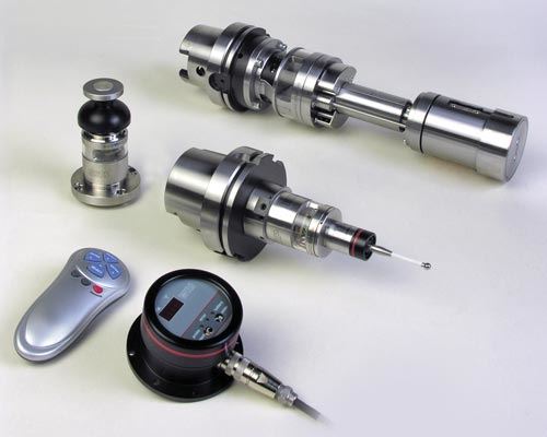
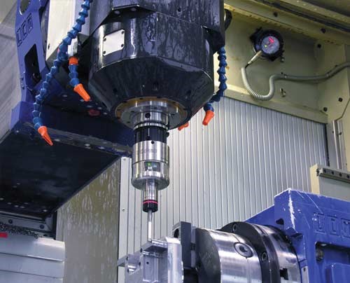
At the low end of the technology spectrum is a touch-type tool setting system. These are commonly used to detect tool presence and/or breakage and to measure the length and diameter of rotary tools.
Touch systems are relatively inexpensive, very compact, and can be wired or wireless. Some, in fact, can be mounted to the machine table with a magnetic base, making them a good choice for smaller machines or machines with large parts, where space is at a premium. They can also often share radio frequency or optical communication hardware with spindle probes, further reducing their total installed cost.
Since they literally “touch” the tool, speeds and feeds cannot be very high. This limits their ability to detect unbalanced tools, most speed- and temperature-related spindle variations and a whole range of other characteristics including broken inserts on multi-insert cutters. Touch systems are also relatively slow, often requiring precious seconds to perform a tool breakage and tool measurement cycle.
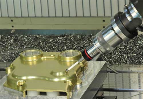
While typically not used for tool inspection, spindle probes and wireless bore plugs are also touch devices that often are used to inspect features of the workpiece while it’s on the machine. When coupled with powerful, modern SPC and 3-D analytical software, a spindle probe or a bore plug can reduce, or in some cases even eliminate, the need to do in-process inspections on a CMM. Wireless bore plugs can be a very critical tool for providing in-process bore size data in microns for use by self-adjusting boring bars.
Feedback from the spindle probe and the bore plugs can be combined with dimensional data from the toolsetter to generate wear-based tool offset adjustments. Even at the most basic level, such a system can significantly reduce the incidence of out-of-spec features requiring re-machining after the final CMM inspection.
Non-Contact
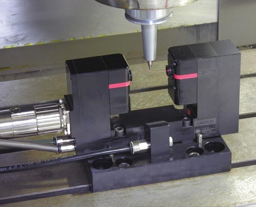
The other option for tool inspection is a non-contact system, which today almost always means a laser-based device. A laser can measure a tool rotating at virtually any practical cutting speed, which means that speed- and temperature-related spindle variations can be detected along with out-of-balance conditions. And unlike last-generation systems, today’s lasers are virtually unaffected by the presence of coolant mists or droplets on the tool or in the air.
Lasers also are very fast. A modern system can perform a breakage check; map the full dimensional profile of the tool; and check each individual insert profile in a multi-insert tool in a matter of few seconds. Moreover, the laser system can perform these checks while the tool is spinning at full cutting speed and moving at rapid traverse velocity.
Lasers are the only practical choice for very large machines, with systems available for distances up to 15 meters (50 feet) between the transmitter and receiver. Even with that range, such systems can make measurements to a repeatability of 1 micron or less.
At the other end of the size spectrum, a high-precision laser system can measure to 10 microns on a spinning tool, but only has a maximum range of 32 millimeters. These find application on small, ultra-precision machine tools often found in mold shops serving the electronic and medical industries.
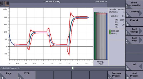
Inspecting tools before and after they are in the cut provides size information that can be used to check tool presence and compensate for wear, but it provides no data about what is actually happening during the cut. That is the function of a tool monitoring system, which fills the vital information gap and makes it possible to bring the whole process under real-time control.
These systems use sensors to detect operational conditions including strain and force; power consumption; acoustic emissions; vibration and acceleration; torque and force; and, coolant temperature and flow. The sensors can be integrated into components like drives and spindles on new machines, or added on as external devices on existing machines.
In either case, sensor data is processed to create a real-time signature for the operation. Obviously, the sensors will detect potentially catastrophic events—such as crashes or tool breakage—and provide feedback to minimize any damage to the machine or workpiece.
This capability alone makes a monitoring system worthwhile given the high-value of machines, tools and workpieces in the moldmaking industry. Of even greater potential value, however, is the ability to use the data to optimize a tool’s performance in the cut via an adaptive control strategy.
Real-time data on what is happening in the cut allows the control system to adjust cutting parameters “on-the-fly” to achieve optimal metal removal rates, optimal tool life or any combination of the two that will result in optimal profitability for the operation. Tool monitoring alone has demonstrated cycle time reductions of up to 20 percent in a range of milling and drilling applications in the auto industry.
Summary
The net result of integrating efficient tool inspection before and after the cut with optimized tool performance in the cut is the reduction to near zero of “Garbage In” for mold manufacturing applications. And, the assurance of quality inputs made possible by inspection and monitoring moves the industry one step closer to the total elimination of “Garbage Out”, while improving both productivity and profitability.
Related Content
Hands-on Workshop Teaches Mold Maintenance Process
Intensive workshop teaches the process of mold maintenance to help put an end to the firefighting culture of many toolrooms.
Read MoreLaser Welding Versus Micro Welding
The latest battle in finely detailed restoration/repair of mold materials.
Read MoreWhat is Scientific Maintenance? Part 2
Part two of this three-part series explains specific data that toolrooms must collect, analyze and use to truly advance to a scientific maintenance culture where you can measure real data and drive decisions.
Read MoreRead Next
Benefiting From Advanced Probing Technology
A progressive moldmaker uses the latest probing technology to attack downtime.Data Import Utility : Edit Content
Read MoreHow to Use Strategic Planning Tools, Data to Manage the Human Side of Business
Q&A with Marion Wells, MMT EAB member and founder of Human Asset Management.
Read MoreAre You a Moldmaker Considering 3D Printing? Consider the 3D Printing Workshop at NPE2024
Presentations will cover 3D printing for mold tooling, material innovation, product development, bridge production and full-scale, high-volume additive manufacturing.
Read More
