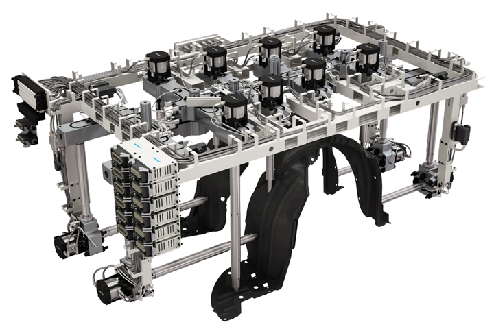
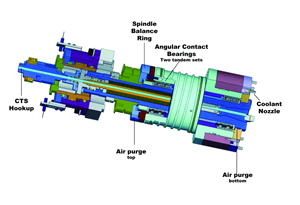
Many molds require complex hot runner systems, like this one, which features a sequentially controlled valve gate system with nozzles on the top and sides. The communication of comprehensive data between the molder/OEM, moldmaker and hot runner supplier early on will ensure the right hot runner system is built for the job. Photo Credit, all images: PCS Company
Too often, mold builders tasked with delivering a complete, production-ready hot runner mold work in haste to design the mold and system. They look online and order what they believe is needed but realize too late that the various components won’t fit or work together as expected. If decisions are rushed or poorly informed, the result will likely be a poor-performing mold and system. To eliminate costly errors, making time for precise and proper communication between the molder, mold builder and hot runner supplier is essential.
It’s a Team Effort
The molder/OEM typically chooses the hot runner supplier based on its expertise in a specific market segment. The mold builder leads the project and collects the necessary information. This information flows from the molder to the mold builder and then to the hot runner supplier.
Making the time for precise and proper communication with the molder, as well as the hot runner supplier, will eliminate costly errors.
When a new mold is being quoted, the experienced mold builder should know what questions to ask the molder/OEM to be able to provide all critical details to a hot runner supplier for a realistic and accurate estimate. This is not always the case, however, because the mold builder’s spec sheets are generally more focused on the mold build. Information gaps regarding hot runner criteria can, and often do, lead to delays.
Remember that the hot runner supplier is responsible only for ensuring that its hot runner system delivers plastic efficiently to the mold. So, the supplier’s spec sheets are specific to the molding requirements, such as types of gating and the system’s interfaces with the molding machine and the mold.
The mold builder designs the core and cavity, cooling channels and mechanics within, which all play a significant role in the mold’s cycle time and performance. Communicating openly with the molder/OEM and hot runner supplier ensures the data is complete and that the mold builder has what is needed to build a successful, profitable hot runner mold.
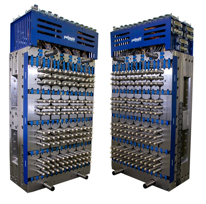
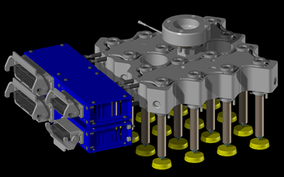
This 144-drop hot half shows very closely positioned nozzles. Nozzle size and spacing are among the critical factors that help determine the size and cost of the hot runner system, mold and molding machine required for optimum production of a given part.
The Necessary Details
While the mold builder works closely with the hot runner supplier to design the system, the molder must be part of this collaborative process by providing the following details:
- The specific grade of plastic to be molded.
- Will there be a mix of regrind material or will the product be molded from recycled or biodegradable plastics? Analysis tools such as flow simulation need grade-specific information to predict accurately. If resin specs are unavailable, consult the plastics supplier’s technical resources.
- Color changes, gas-assist, foaming agents and other factors that may impact the design.
- 3D geometry along with a 2D part drawing indicating all critical-to-function details, such as tolerances, areas where gating is not permitted and surface finish requirements.
- Instructions to simplify or expedite hot runner design, such as the preferred gate location or permission for a vestige.
- Product designer contact information for minor modifications to the part design, such as adding a dimple, post or tab for convenient gating and improved flow.
- Molding machine specs and auxiliary equipment information to ensure compatibility between the mold, hot runner and molder’s setup.
- Electrical voltage, controller and connector types, zone limitations and mounting locations.
- Hot half servicing requirements while the mold is in the machine, such as rapid replacement of tips, needles, heaters and thermocouples.
- Pneumatic, servo or hydraulic preferences for valve gate systems.
- Process configurations, including:
- Water connector location and size preferences.
- Mold clamping arrangements such as magnetic or quick mold change setups.
- Cavity ID and nozzle zone ID which usually coincide to avoid troubleshooting or assembly mishaps.
- Stamping or etching requirements, such as “0” corner, top of mold and operator side.
- Mold lifting and handling preferences.
The molder/OEM is the principal source for all information. For a successful mold (and hot runner) build, it is essential that they provide all critical requirements to the mold maker.
Gate Design Considerations
Designs can begin only after deciding on gate location(s), so the mold builder must check the part design by asking the following questions:
- Does the product design restrict gate marks or vestiges in specific areas due to aesthetic requirements? Also, consider knit lines, splays and blemishes.
- Can there be areas where gate vestige will cause injury or interfere with surrounding components in assembly? For example, components for medical products and barbs on parts for air or liquid flow systems.
- Are there critical, high-tolerance requirements such as flatness and roundness? Gate location influences these parameters.
In some cases, indirect gating by a hot-to-cold runner system may be the solution. Where there are restrictions, a tab or post can be added if it is convenient for fill, provided the part design enables adding one. For some products, gating from the core or underside of the mold may be the only solution, which imposes many restrictions on the mold design, as ejection may be necessary on the fixed half.
It is also possible to gate on an angle, contoured surface or from the side. However, these designs increase hot runner costs and require tedious assembly procedures. Also, consider part and gate cooling requirements and verify conditions in all locations if more than one gate is necessary to fill the part.
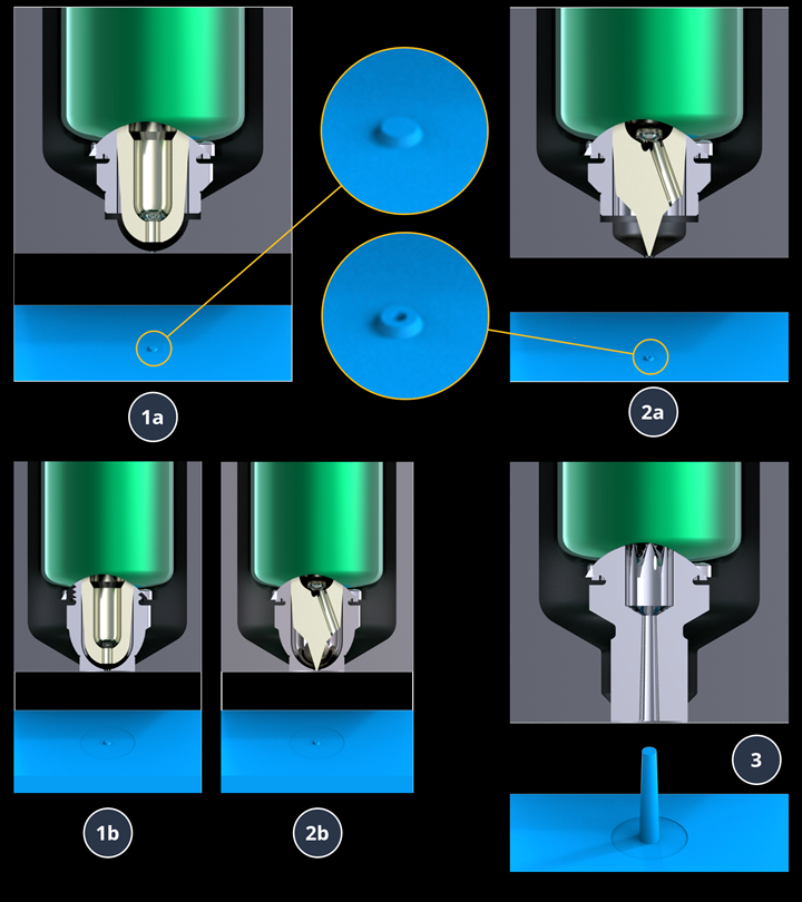
Some thermal gate tip options are illustrated here. The molder must specify what type of vestige, if any, is acceptable on the molded part so the moldmaker and the hot runner supplier can determine the best tip style for the application.
Thermal gates offer various tip and needle styles. Valve gating is another option to mitigate the issues with thermal gates. They are 1.5 to two times more expensive than thermal gates but are often worth the investment.
A sequential valve gate system may be necessary to meet product finish and quality specifications in parts requiring multiple gates. The ability to time each gate’s open and close sequence helps manage end-of-fill and knit lines and eliminate gas traps.
After identifying areas for potential gate location, use a flow analysis to determine the optimal flow and fill balance. Always remember “thick to thin” — gates should be placed in areas with thicker wall sections.
The hot runner supplier needs to design the system to address the residual time of molten plastic, to prevent material degradation in the hot runner.
Here are a few key factors to consider that influence gate and hot runner design:
- Melt flow Index (MFI) in combination with wall thickness and flow length. Lower MFI resins such as polycarbonate (PC) require higher pressure and larger gates to fill.
- Fillers and additives play a significant role in flow character. For example, glass fillers and flame-retardant additives increase injection pressure and temperature requirements. Filled materials usually require larger gates.
- Semicrystalline resins like polyacetal (POM) and nylon need tighter temperature control due to a narrow window between their melt and freezing temperatures. Pay attention to the residual time of molten plastic within the manifold and nozzles to avoid material degradation or interrupted production. The hot runner supplier engineers the system and provides guidelines to manage this efficiently. Well-positioned thermocouples and highly responsive heating components are required.
- Co-injection, gas-assisted, foam or MuCell molding and frequent color change requirements should be discussed early in the project.
- Materials like polyvinyl chloride (PVC) release corrosive gases and require corrosion-resistant material plus special coatings in the hot runner system.
With the correct information, estimating and quoting processes will flow smoothly for the mold builder and hot runner supplier. Always leverage each party’s expertise because effective communication and collaboration will yield a quality mold and hot runner system.
Related Content
The Benefits of Hand Scraping
Accuracy and flatness are two benefits of hand scraping that help improve machine loop stiffness, workpiece surface finish and component geometry.
Read MoreLaser Welding Versus Micro Welding
The latest battle in finely detailed restoration/repair of mold materials.
Read MoreSolving Mold Alignment Problems with the Right Alignment Lock
Correct alignment lock selection can reduce maintenance costs and molding downtime, as well as increase part quality over the mold’s entire life.
Read MoreMachining Center Spindles: What You Need to Know
Why and how to research spindle technology before purchasing a machining center.
Read MoreRead Next
How to Transition From a Cold to Hot Runner Mold
Reducing cycle time and costs while also freeing up your machines for other projects are advantages gained by using hot runners that no one can ignore. But where does one begin transitioning from cold to hot runners?
Read MoreHow to Use a Conformally Cooled Sprue Bushing to Reduce Cycle Time and Ease Cost Pressures
Use of a new conformally cooled sprue bushing helped solve Midwest Mold Services’ problem with a big sprue that was hard to cool and preventing faster ejection times.
Read MoreVIDEO: Taking a People Before Product Approach to Growing a Business
Angela Elsey, President of PCS Company, shares her journey into moldmaking, perspective on the industry and plans for the business.
Read More


