Five-Axis Inspection for Moldmakers
Does five-axis inspection offer similar benefits in speed and accuracy for moldmaking operations?
A five-axis measuring head and probe system can produce impressive results in the measurement of feature-rich parts—such as powertrain components and complex, doubly-curved surfaces—including those found in aerofoils and turbine blades. For example, the time taken on a measurement application involving a range of aero-engine blisk features was reduced from 46 minutes to 4 minutes 30 seconds, while the time needed to inspect 12 valve seats and guide bores on an automotive cylinder head was cut from nearly 30 minutes to just 3 minutes and 42 seconds. After reading these results, many moldmaking companies are asking whether five-axis inspection offers similar benefits in speed and accuracy for their companies.
Understanding Faster Measurements
To answer this, it is first important to understand how the faster measurements are achieved in production manufacturing operations. The major limitation of conventional, three-axis scanning is that any attempt to move rapidly the large mass of a coordinate measuring machine (CMM) in a non-Cartesian trajectory results in inertial errors caused by accelerations and decelerations. Therefore, the only possible way to maintain acceptable accuracy is to reduce the measuring speed.
Five-Axis Inspection Benefits
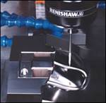
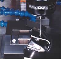
The key to the time savings with five-axis inspection is the ability to overcome this limitation. The technique uses synchronized head and machine motion when scanning, allowing the probe to follow changes in part geometry rapidly without introducing dynamic errors. As a result, the CMM is able to move at a constant velocity while measurements are being taken, without impacting accuracy.
The second benefit of five-axis inspection is the ability to increase measurement accuracy by using tip-sensing probes. Most moldmakers are familiar with using five-axis machining and the benefits of using shorter cutters. This is possible because of the ability of a five-axis machine to lower the head toward the part and then orient the cutter onto the surface. With three-axis machining longer cutters must be used to reach the surface, which are inherently less accurate. In a similar way, five-axis inspection measures very close to the part surface. This means that shorter probes can be used, so giving greater inspection accuracy.
The Software Element
As well as needing the latest scanning technology, successful application of five-axis inspection also requires the use of appropriate inspection software/program that supports the use of the new probe for the verification of both geometric and free-form shapes on all major makes of CMM.
The development work required for five-axis inspection on CMMs has benefited from the considerable work undertaken for many years to produce systems for use with portable inspection arms. These devices are capable of multi-axis inspection because of the degrees of articulation in the arm. As a result, the supporting inspection software has always needed the ability to process measurements from probes that are constantly changing their orientation. Similarly, the use of laser scanners on these arms has required software that can handle the large amounts of data generated. Such systems can process the greater volume of measurements taken on CMMs using five-axis inspection.
The development of five-axis inspection software also has used technology initially generated to support five-axis machining. As well as using similar routines to drive the five-axis movement, the new inspection software also has benefited from being able to incorporate proven five-axis simulation and collision detection technology from machining systems. In the same way that computer models of machine tools can be used to simulate the machining process, models of the most common types of CMM have been developed so that the operation of the whole system can be monitored, not just the movement of the probe around the part. This enables the complete inspection sequence to be developed and tested offline on the computer before being run on the CMM. As a result, users can be confident that the inspection routines will operate safely and efficiently—without any risk of collisions that could damage the probe or the part.
Mold Application
Whether toolmakers can gain the same benefits from five-axis inspection as the manufacturers of complex aerospace and automotive parts will depend on the size and complexity of their molds. Manufacturers of very large or, more specifically, very deep tools should obtain more accurate results with the five-axis approach because of the ability to use shorter, tip-sensing probes. For firms making smaller and simpler molds a three-axis CMM may well provide perfectly adequate inspection reports but, as applications vary greatly, the five-axis technology should at least be investigated to determine any increase in measurement speed that might be possible.
Companies that are making tools incorporating complex designs, and those needing to machine particularly accurate surfaces, will be able to take more measurements with a five-axis system, and take them more quickly, and so give more complete inspection reports to their customers. This could be especially important for those firms making large tools for composite components, such as wind turbines or truck cabs and fenders.
Whole-Mold Inspection
The final benefit will come to those companies measuring tools that have to produce parts with undercuts. While a three-axis CMM will be capable of measuring the individual components in the mold, it will not be able to reach the undercut areas in the tool once it has been assembled. The five axis approach will allow all areas of the complete mold to be measured, again giving the company the ability to provide a more comprehensive inspection report to the customer.
Related Content
Tips for Tackling Mold Design, Machining, Cutting Tool and Wear Challenges
Tips for tasks ranging from reducing risk in part design and taking advantage of five-axis machining to refining cutting tool performance and reducing wear with guiding and centering systems.
Read MoreHow a Small Programming Change Cuts Cycle Time in Half
Overriding the CAM system when milling a series of lifter pockets helps to improve metal removal rate and increase feed rates.
Read MoreWhat is Scientific Maintenance? Part 2
Part two of this three-part series explains specific data that toolrooms must collect, analyze and use to truly advance to a scientific maintenance culture where you can measure real data and drive decisions.
Read MoreHow to Fix Predicted Warpage Before It Happens with Windage and CAD Model Morphing
Applying windage and model-morphing techniques saved toolmaker/molder Sturgis Molded Products the time, cost, headaches of multiple part/mold design iteration loops, cumbersome cooling fixtures, and long molding cycles.
Read MoreRead Next
Choosing CAD Software For 3D Mold Design
The world of CAD offers many alternatives to shops that want to use the latest 3-D technology for their mold design. This article looks at the benefits of the various approaches and offers some tips on choosing the most appropriate one.
Read MoreBringing Greater Process Control to Moldmaking
Advances in machine accuracy, on-machine probing technology and non-contact toolsetting provide powerful tools for automating and speeding mold machining.
Read MoreHow to Use Continuing Education to Remain Competitive in Moldmaking
Continued training helps moldmakers make tooling decisions and properly use the latest cutting tool to efficiently machine high-quality molds.
Read More


