Controlling Your Hot Runner Manifold System
Moldmakers and molders need to better understand modern hot runner controller technology to solve processing problems.
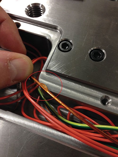
Say you receive a call from a molder explaining that the mold you just delivered is encountering hot runner manifold issues that resulted in a failed sample. Your customer asks you to correct the issue and return the mold within 24 hours. Later, it’s discovered that the problem actually was caused by a power pin pushed into the connector to the cable at the press. One way to prevent this type of problem from occuring in the first place is with proven technology like modern hot runner controllers, which can save time and provide accurate information to help identify plastic injection molding problems more quickly.
The first job of a hot runner controller is optimal performance. It should accurately maintain the targeted molding set point while detecting and communicating issues. And it should be built for a harsh enviroment.
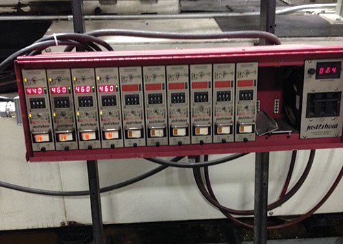
External power card controllers are the most common type of hot runner controller and are capable of powering heaters and providing basic diagnostic information on the heating and temperature circuts. Typically, they include one card per heat zone that slides into a housing. The most common configuration is 15 amps per card, although other amperage configuarations are available.
With this type of controller, cards can be removed and installed while the controller backplane is under full power, and can be left out of the controller cabinet while being used. Cards from different OEMs can be mixed or matched into the same housing, and if there is a problem with a particular card, the user can swap it with cards from another controller or zone. Pulling the card out from the housing and replacing it with a new card can be a very efficient way to fix a problem. However, if the “bad” card is not thrown away, it will just become someone else’s problem. (Caution: Pulling cards under power and reinserting them can result in electrical shock to the user and damage to the card and controller.)
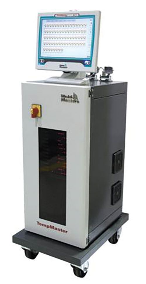
Touchscreen internal card controllers offer greater capabilities, security and accuracy in the application of power and reporting temperatures. Some common features include:
1. Mold test/wiring diagnostics, a feature every moldmaker should take advantage of prior to shipping a mold. It provides the ability to pre-heat the system, test it and then save the results as proof that the system performed as designed before it left the plant.
2. Tool storage (program setup) that saves the hot runner system’s set point on the hot runner controller. This set point can then be called up repeatedly, preventing changing of a set point by mistake.
3. Plastic leakage detection designed to protect the manifold system from becoming over-molded, creating unplanned downtime and damage.
4. Leading zone detection/uniform heat feature that detects the slowest heating zone and then regulates the percentage of power that all other zones receive during the heating phase. This ensures that all the plastic inside the system is at the same uniform temperature, preventing unplanned overheating and resin degradation. The actual value of the slowest zone is the temporary set point of all other zones.
5. Slave zones that allow the use of a heating zone with the same properties when a thermocouple (TC) fails or is wired incorrectly. The TC signal information from the zone being slaved is used to control the power output to the zone that has a TC issue. This can be done on multiple zones, if needed.
6. Purge wizard that permits pre-configured set-point temperatures and times to run at a specified temperature prior to purging the manifold system. This can be used for color changes or with extremely small shot sizes when residence time is an issue and when fresh material is required.
7. Machine Input Output (IO) communications that provide the means for the molding machine and the hot runner controller to communicate. When preset limits on the hot runner controller (sequential valve gating and water monitoring options) are exceeded, the press can be stopped from the hot runner controller. The inverse also applies. This prevents damage to the molds, machines and auxiliary equipment.
8. Water flow monitoring with Reynolds number calculations, an advanced feature that can be run within certain hot runner controllers. It allows any of the monitored parameters that go outside the preset limits to stop the press when the controller is connected to it.
9. Sequential valve gate (SVG) control, which can be added to the hot runner controller in the form of an internal card. The SVG capabilities can be accessed throught the common interface of the touchscreen. Combining features like this into the hot runner controller can save floor space and make use of a common interface for multiple functions.
10. Username and password security, providing system-level access and monitoring of changes and production-run history.
11. Network capability that allows access to the controller from anywhere within or outside of the plant, allowing fewer process engineers to cover a wider number of systems or plant locations through the following type of connections: LAN networking using Ethernet, Modbus, SPI or a VNC protocol; wireless networking using an iPad or Android device, or plant Wi-Fi using a centralized tool setup/store on the company server. It also allows remote control for service.
12. Multiple controllers that are controlled from one location, for example, from a PC, smartphone or tablet.
Modern hot runner controller technologies are not without their challenges. Certain connection types use cables, allowing for connection failures or inconsistencies. For example, the connection pin has barbs on its sides that are used to retain the pin in the plug, but this can be problematic over time. In addition, many heaters fail when moisture is present inside the heater. The “softstart” feature available on most controllers enables that moisture to be safely removed, preventing heater failure.
Most hot runner manifold systems use 230-volt single-phase heaters. A transformer is required if a plant’s power source cannot accommodate this. The location and heat of such transformers is also something to consider. Some transformers can be intregrated into some hot runner controller models. Creating a standard for hot runner controllers via a common interface increases consistency and reduces user error, both at the mold builder and the molding facility.
Related Content
Fundamentals of Designing the Optimal Cooling System
The right mold components can help improve mold cooling and thereby produce higher-quality parts.
Read MoreMachine Hammer Peening Automates Mold Polishing
A polishing automation solution eliminates hand work, accelerates milling operations and controls surface geometries.
Read MoreRevisiting Some Hot Runner Fundamentals
What exactly does a hot runner do? If you’ve been in the injection molding industry for any length of time, you might think the answer is obvious, but it is not.
Read MoreMaintaining a Wire EDM Machine
To achieve the ultimate capability and level of productivity from your wire EDM on a consistent, repeatable and reliable basis, regular maintenance is a required task.
Read MoreRead Next
Considerations for Assessing Robotics Requirements
Knowledge of part de-molding, end-of-arm tooling construction, part defects caused by the mold-robot interface and available automation options is key for suppliers looking to add greater value.
Read MoreDesigning a Better Heat Exchanger - Part 1
In a three-part sub-series, we review considerations for mold water cooling systems.
Read MoreControlling the Melt Delivery System Heat Source
Understanding the heating systems along the melt delivery path is critical to setting up a robust process and properly diagnosing problems.
Read More
