Considerations for Assessing Robotics Requirements
Knowledge of part de-molding, end-of-arm tooling construction, part defects caused by the mold-robot interface and available automation options is key for suppliers looking to add greater value.
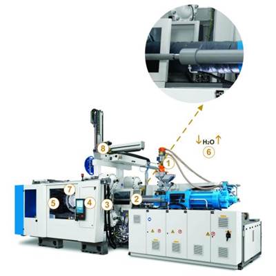
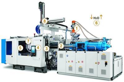
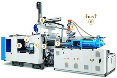
This series of articles provides an explanation of each step in the molding process, as a pellet is transformed into a part. This article will focus on opening of the mold, the ejection of the part and the automation involved, whether the parts are dropped, vacuumed or picked out of the mold. The molder’s robotic capabilities, combined with the end-of-arm tooling (EOAT), directly impact mold design, cycle time and cost. Here, we will review using a robot to pick the part out of the mold.
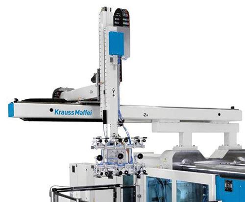
One of the goals of every project is to get all parties involved communicating and working together to engineer the best plan. In addition to the many other benefits, this ensures that the correct automation equipment is purchased. There are many types of robots. Two industry standards are linear and articulated. Linear robots are typically less expensive, enable faster part removal from the mold and are easier to program. However, they offer less articulation of the part and are less useful for post-molding. Because linear robots move in a linear fashion, they are often restricted to an X, Y or Z plane, and do not provide freedom of positions similar to a human arm. Linear robots can be installed on the operator or non-operator side of the press or at the end of the press (L mount).
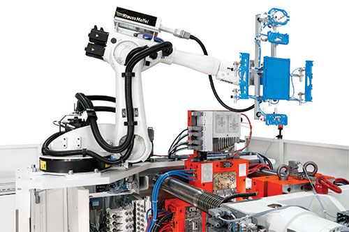
Articulated robots are multifunctional, more useful for post-molding and can be configured for tight spaces because of their human-arm-like flexibility. They are typically mounted on the floor beside the machine or on the machine-fixed platen. For example, in post-molding applications, such as assembly or packaging, articulated robots allow orbital positioning that is customized to the position that the part needs to be in to execute the operation. However, these robots require more room and are often more difficult to program because of these orbital positions. They are also typically more expensive and offer slower removal of parts from the mold.
EOAT is another important factor. Oftentimes, molders select the least expensive EOAT configuration, which can yield an inaccurate design that is unable to maintain the tolerances necessary to operate within the process allowances.
Wrist motions are another robotic consideration. Traditionally, linear robots are supplied with 90-degree pneumatic rotation from vertical to horizontal, which is adequate in most pick-and-place applications. Yet, more often, additional degrees of freedom are required to conduct post-molding applications or to simply relieve the part from the mold. Many newer automation applications have parts designed with detail that is not in the die draw, which requires the robot to “wiggle” the part off of the mold. This requires a servo wrist that essentially adds a two-axis articulated motion to the end of the vertical arm on a linear robot.
The type of wrist paired with the robot can directly impact mold design. For example, it affects daylight, or mold-open distance, which is the amount of linear clamp stroke required to open the mold far enough for a robot to remove parts. A dual-opposing wrist design for insert molding can minimize the daylight opening by 25 percent, simplify programming and reduce mold-open time, all which improve cycle time.
Considerations for wrist options include torque requirements, wrist weight, weight of payload (parts and runners), and the extra daylight needed for wrist, payload and movement. In a nutshell, wrist choice is dictated mostly by application requirements, but sometimes excessive torques or minimal daylight requirements can play a bigger role in this choice. These facts are often overlooked, resulting in premature failure of components or utter dysfunction of the automation.
Tolerances in automation cell design are another consideration. A robot has a given operational positioning tolerance. However, this typically cannot be relied upon for position accuracy in the cell, because the entire cell’s stack-up of tolerances are often far beyond the controlled allowances of the final part print. Also, keep in mind that the robot is sitting on a moving machine. Thus, for a tight toleranced automation cell, it is better to eliminate the robot from the stack-up of tolerances by considering the robot as only a carrier of the EOAT in which the EOAT, mold and automation fixtures are operating parts of an isolated system. To ensure tighter tolerances, locating pins are often used to ensure proper datum location among the three pieces of that three-part isolated system.
Vibration is often the leading challenge to position tolerance. Consider that a robot mounted to a machine platen has a moving piece of machinery under it, so it’s no surprise that holding a position tolerance is difficult. Forces of an operational molding machine travel in a sine curve. When that sine curve terminates at the EOAT, it becomes high-frequency vibration.
Reason: the sine curve movement of the molding machine transfers through masses of metal, and more mass allows low frequency, while less mass promotes high frequency. As that sine curve of vibration moves from fixed platen to robot riser to traversing beam to kick stroke to vertical arm and then to the EOAT, the mass is reduced exponentially, and this excessively increases vibration. The solution is to ground the vibration by adding a support leg with enough mass in proportion to the robot. This provides a path for transfer of those forces to a vibration-isolation pad to the floor. The bigger the leg, the more the mass, the easier it travels and the less vibration.
These basic robot considerations will help the molding team provide a complete and consistent molding process.
Related Content
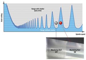
How to Eliminate Chatter
Here are techniques commonly used to combat chatter and guidelines to establish a foundation for optimizing the moldmaking process.
Read MoreHands-on Workshop Teaches Mold Maintenance Process
Intensive workshop teaches the process of mold maintenance to help put an end to the firefighting culture of many toolrooms.
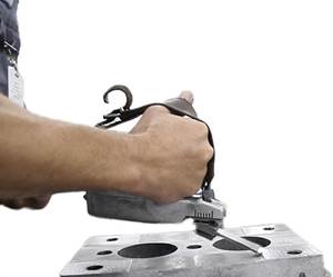
Read MoreThe Benefits of Hand Scraping
Accuracy and flatness are two benefits of hand scraping that help improve machine loop stiffness, workpiece surface finish and component geometry.
Read MoreIt Starts With the Part: A Plastic Part Checklist Ensures Good Mold Design
All successful mold build projects start with examining the part to be molded to ensure it is moldable and will meet the customers' production objectives.
Read MoreRead Next
Initial Pellet Contact is the Screw
Here’s what every moldmaker should know about an injection molding machine’s reciprocating screw, which is often misunderstood and applied to the process incorrectly.
Read MoreDesigning a Better Heat Exchanger - Part 1
In a three-part sub-series, we review considerations for mold water cooling systems.
Read MoreControlling the Melt Delivery System Heat Source
Understanding the heating systems along the melt delivery path is critical to setting up a robust process and properly diagnosing problems.
Read More
