A Strategy for Better Mold Finishes
Combining advanced tool geometry and complementary CAM tool paths can reduce finish cycle times and improve surface quality.
Within this decade, advanced carbide cutting tools used with constant-chip-load CNC cutting strategies have dramatically increased material-removal rates in roughing of mold cores and cavities. The combination of these tools and strategies also results in dimensions closer to near-net shape, which favorably impacts subsequent finishing operations. As impressive as these roughing approaches have been, however, they are rarely used for finishing cycles, which account for the bulk of the machining time required for most mold cores and cavities. More than anything else, reducing the time it takes to machine a core and cavity feature to the desired surface finish will significantly reduce a mold’s overall CNC manufacturing costs.
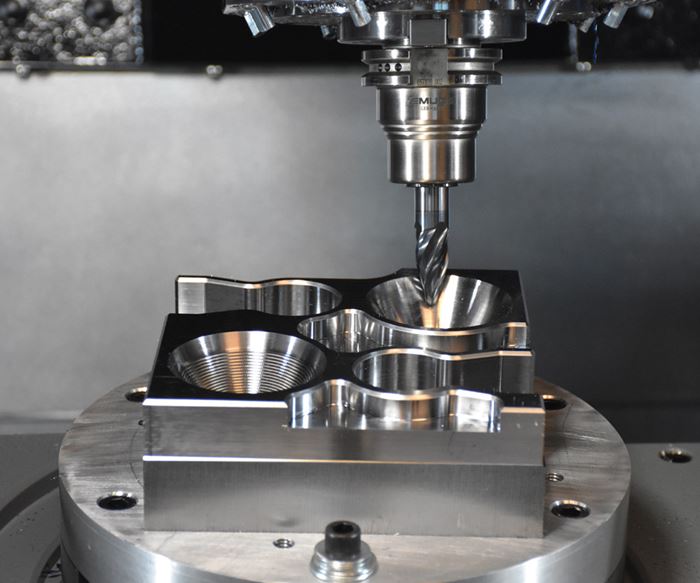
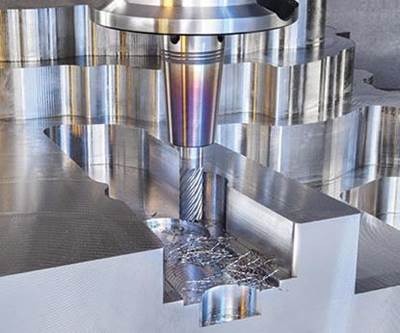
For some time, manufacturers of solid carbide tools and CAM suppliers have been working together to dramatically reduce roughing cycle times. Now these partnerships are expanding into improving finish passes, and automated CAM tool paths are driving innovative cutting tool geometry and vice versa. One example of this is the emergence of new circle-segment cutting tools designed for use with automated CAM tool paths for finishing. In many cases, this combination can dramatically reduce finish cycle times compared with the use of more traditional ball end mills.
Switching the Tool Geometry
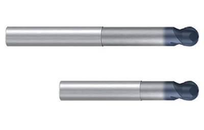
Ball end mills have been the go-to cutting tool for surface finishing for decades. They are easy to program, and they can successfully reach into tight areas of parts. However, for parts that require a great deal of surfacing, ball end mills are part of the problem rather than the solution when the goal is better surface quality along with reduction in machine cycle times.
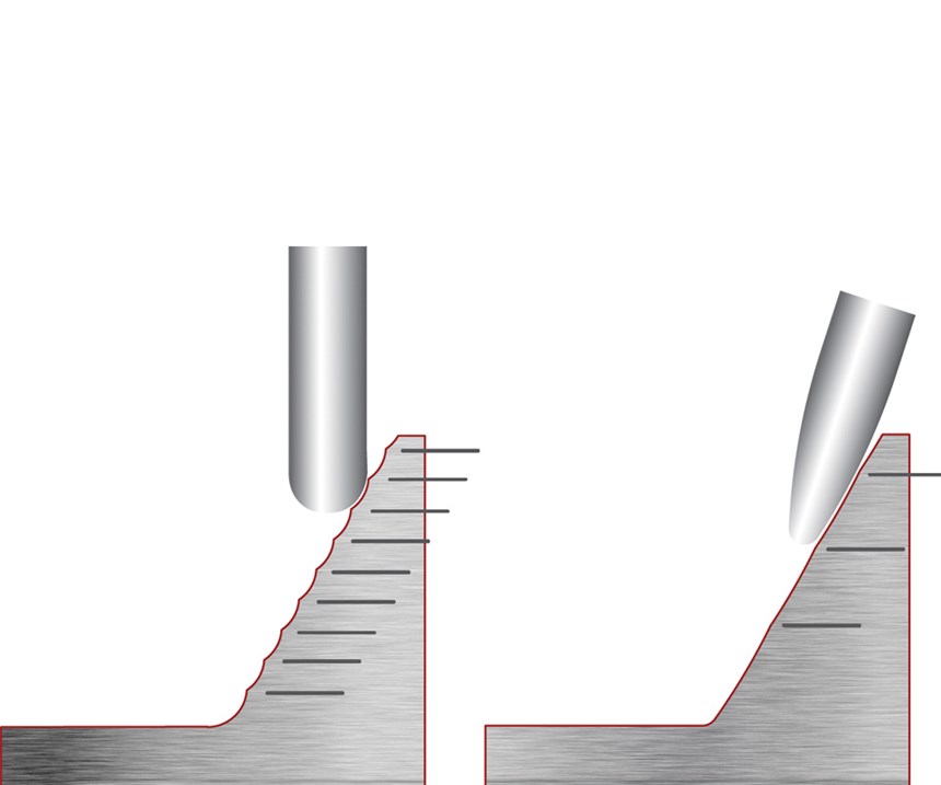
This is because ball end mills must be used with very small stepovers in order to reduce the size of cusps in the material. Compensating for this staircase effect and achieving the desired surface finish requires a proportionally small stepover or stepdown, typically 3 to 5 percent of the tool’s diameter. Although this will improve the surface finish, it also reduces the amount of surface area engaged by the tool, requiring it to take many passes to achieve the desired finish. This increased number of passes is why finishing requires a bigger time investment than roughing cores and cavities.
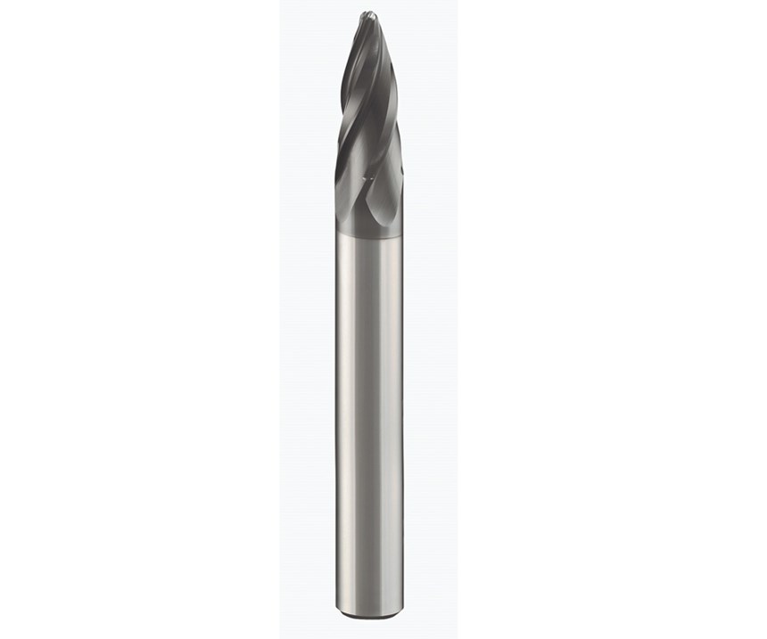
Circle-segment cutting tools are designed so that a small-diameter tool can have a large effective cutting radius. This design reduces the required number of finish passes and the depth of the cusps in the material, producing a better surface finish in a shorter cycle time. The larger cutting radii of these tools (as much as 187 times the cutting tool’s actual diameter) allow extended engagement of the tools with the material and reduce the number of stepdowns required to finish the part. For example, if it takes 30 passes for a ball end mill to finish a set of surfaces, it may take the circle-segment tool six passes to do the same, and do it better.
The Software Component
Circle-segment tool shapes include barrel, oval, taper and lens forms. Each is effective for machining different types of surface geometries, which may be straight, or have minor undulations or draft angles as large as seven degrees. The tools may be used with three-axis CNC machines, but great care must be taken in defining tool planes to ensure the tool is contacting the part in a proper manner and to assure accurate finishing results.
Far better machine cycles can be achieved with multi-axis equipment, particularly machines capable of continuous five-axis machining. With a machine capable of 3+2 indexing, the ability to apply circle-segment tooling greatly improves. The list of applications for applying this technology broadens even further with a machine capable of continuous five-axis machining. Fast, responsive controllers with advanced features like high-speed look-ahead are also advantageous.
To fully take advantage of these tools, however, the programmer/machinist must generate sophisticated programs using CAM software. These programs must continuously present the tool at a precise angle that is dependent on the slope of surface to be finished and the shape of the tool at any given point. The massive amount of code required to create this type of tool path makes it impractical, if not impossible, to write these programs manually.
In this advanced finishing strategy, the circle-segment tools and CAM software need to work in sync to coordinate tool definitions and toolpath behaviors, particularly in 3+2 and simultaneous five-axis machining modes. Circle-segment tools can be used with both three- and five-axis finishing tool paths that the users are already familiar with.
Library support for these tools is also necessary so that the programmer needs only to load the tool definition into the software from downloadable libraries. Then the machining operation will apply the appropriate tool compensation for ultra-high-efficiency finishing. Proficient multi-axis programmers can also fine-tune parameters to make a good finishing tool path even more efficient for specific surface requirements.
Assessing the Opportunity
Evaluating circle-segment tooling is easier if you already have multi-axis equipment and the CAM software. In those cases, you just insert the circle-segment tools into a program you have already run and adjust the stepover/stepdown to achieve a cusp height similar to the one produced by the previous ball tool path (minimal changes will also be required to obtain proper tool plane and axis control), then simulate the program with feeds and speeds identical to the ones used for the ball end mill. This simple time comparison test will reveal the benefits of this alternative finishing strategy.
However, despite the effectiveness of this strategy, it is certainly not time to throw away your ball end mills altogether; there are many surfacing applications for which they are still necessary. It just may be time to evaluate circle-segment cutting tools and automated CAM finishing tool paths for yourself. The reduction in finishing cycle times, subtracting hours of machining time from a moldmaker’s core and cavity work, may make it worth that look. Plus, improved finishes will lower costs by reducing manual polishing requirements.
Watch a short video of circle-segment tools and tool paths in action.
Related Content
How to Fix Predicted Warpage Before It Happens with Windage and CAD Model Morphing
Applying windage and model-morphing techniques saved toolmaker/molder Sturgis Molded Products the time, cost, headaches of multiple part/mold design iteration loops, cumbersome cooling fixtures, and long molding cycles.
Read MoreTips for Tackling Mold Design, Machining, Cutting Tool and Wear Challenges
Tips for tasks ranging from reducing risk in part design and taking advantage of five-axis machining to refining cutting tool performance and reducing wear with guiding and centering systems.
Read MoreWhat is Scientific Maintenance? Part 2
Part two of this three-part series explains specific data that toolrooms must collect, analyze and use to truly advance to a scientific maintenance culture where you can measure real data and drive decisions.
Read MoreTolerancing in Mold Design, Part 1: Understanding the Issues of Conventional Bilateral Tolerancing
Mold designers must understand the location, orientation and form limitations of conventional tolerancing before changing to another dimensioning system.
Read MoreRead Next
Rough Milling: Speed vs. Power
A look at what works in rough milling applications with solid carbide end mills.
Read MoreTips for Successful Hard Milling of Complex Molds
And when mold and die applications demand hard milling of materials up to 66 HRC, using the right end mills, cutting parameters and machining methods is critical for success.
Read MoreReasons to Use Fiber Lasers for Mold Cleaning
Fiber lasers offer a simplicity, speed, control and portability, minimizing mold cleaning risks.
Read More
