A Practical Case for Model-Based Definition
This strategy ensures that all components in the inspection value chain work together, keeping the digital thread intact from design to quality reporting.
In today’s digital-everything world, it is amazing to see how many parts are newly manufactured, remanufactured or modified without the benefit of comprehensive CAD data. In some cases, this cannot be helped, such as with certain maintenance, repair and overhaul situations, in which the original part, once subjected to operational stresses, no longer meets design specifications. Regardless of the reasons, incomplete data is a challenge manufacturing and quality engineers face every day.
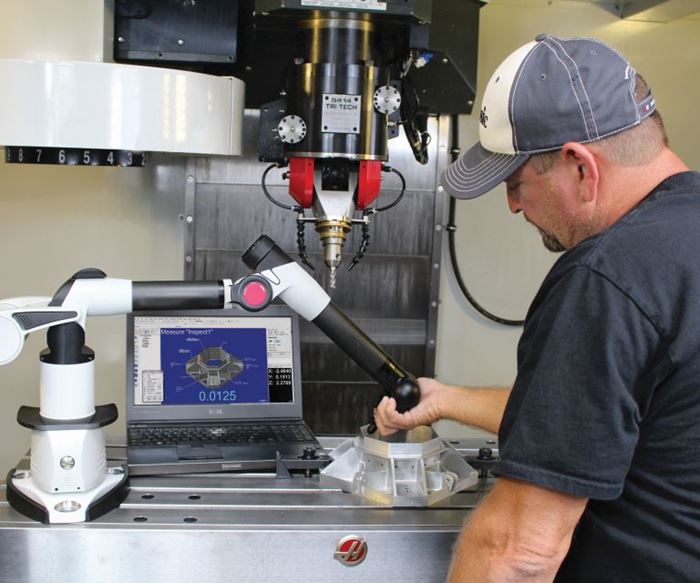
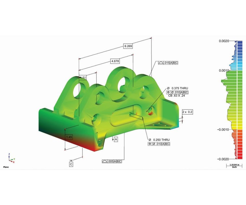
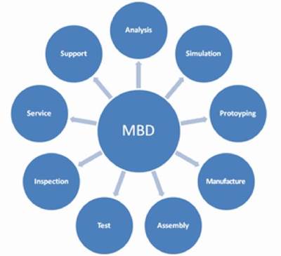
As a way to compensate, many shops are adopting model-based definition (MBD) as a strategy, whereby the CAD model becomes more than the nominal against which all parts are measured and inspected (see Figure 1). MBD keeps the all-important digital thread intact, from design to manufacturing to inspection and quality reporting. Everything that defines the part exists in a single digital archive, including specifications for how to manufacture and inspect it.
Deployment of MBD can be done ad hoc at an individual part or component level, or it can go far beyond this to complete product lifecycle management. For many shops working as sub-contractors, MBD will meet or exceed the requirements for file management, documentation, inspection, reporting and repeatability without the need for a good part to be used as a nominal or comparative for future production. With MBD, everything needed for future production and quality assurance is together, digital and virtual.
Reverse Engineering
If design or manufacturing data needs to be added to a model—for example, a complex surface profile requiring reverse engineering—it easily can, along with geometric dimensioning and tolerancing (GD&T) annotations that will enable accurate inspection of that feature against the model when complete. This is extremely useful to mold builders, in particular, as complex surface profiles can be very difficult, if not impossible, to dimension.
A CAD platform must be at the root of any MBD strategy, including the quality inspection and reverse engineering functions. This will allow the user to import CAD from virtually any platform and increase value through added reverse engineering data, solid modeling, intelligent annotations, inspection and reporting. Modified MBD files must be exportable for manufacturing or back to the native platform from which the CAD data originated. When combined with appropriate digital measuring devices or coordinate measuring machines (CMMs), these files will allow manufacturing and quality engineers to fill in manufacturability data gaps and provide confirmation of design intent through integrated quality reporting.
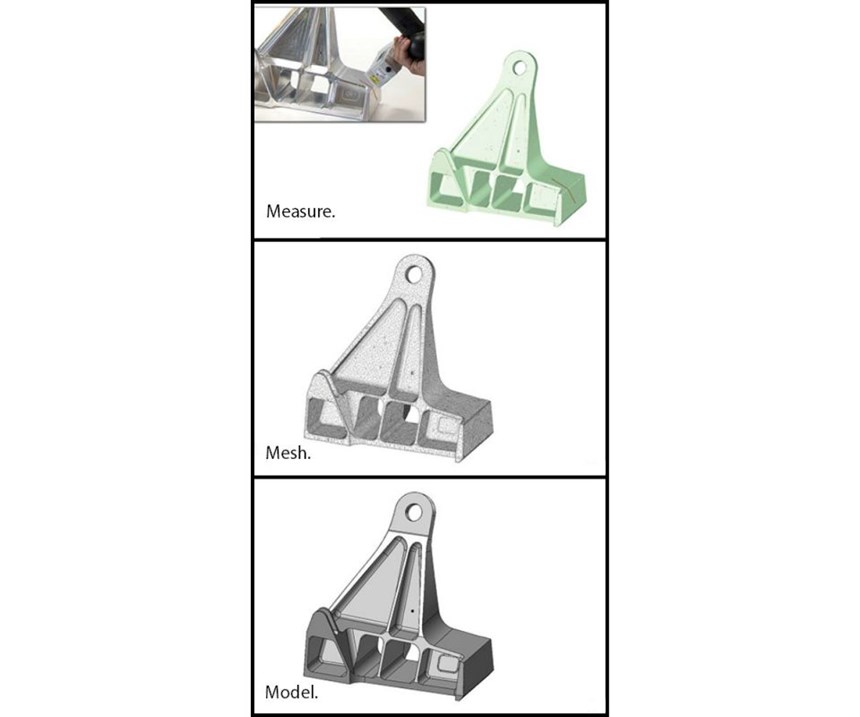
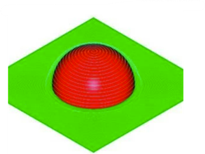
Capturing and then processing data using reverse engineering software is very straightforward (see Figure 2):
• Measure. A suitable CMM or scanner is used to measure and capture 3D surfaces as point clouds, including planes, cylinders, cones, spheres, lines, splines, circles and slots. As the term “point cloud” infers, the collected data is a group of relative points in space without any connecting structure or geometry among them.
• Mesh. Reverse engineering software “connects the dots” of the point cloud data, applying geometry to create a watertight mesh or STL model ready for surfacing also suitable for 3D printing. This process includes alignment and merging of meshes, filtering, smoothing, and filling holes. For some applications, like 3D printing and additive manufacturing, this step is as far as is needed.
• Model. Reverse engineering software automates the conversion of mesh models to 3D non-uniform rational basis spline (NURBS) surfaces and solid models. The solid models can be made intelligent by adding associative GD&T annotations before they are exported to any popular CAD format to support other manufacturing applications and databases.
Quality Inspection
Quality inspection and reporting used to be a disparate process isolated in a quality lab. Today, in-process inspection is much more integrated with the production floor. In the MBD process, it is the job of inspection software to align and compare the nominal CAD model with measured points collected from the finished part, whether that includes a relatively small number of manually triggered contact points or non-contact, scanned data containing millions of points.
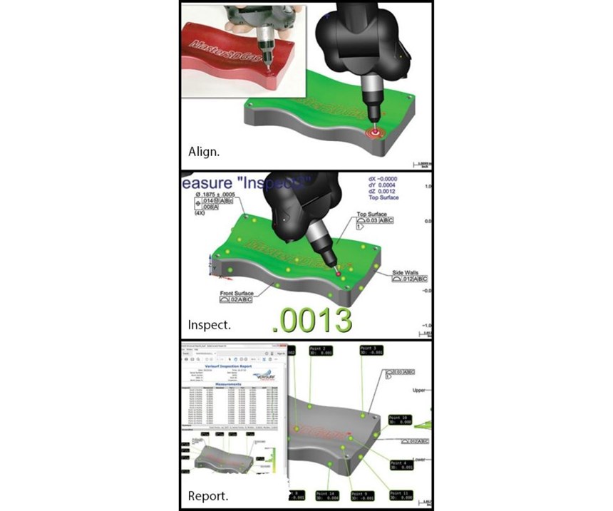
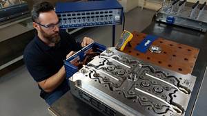
For example, model-based inspection software uses a simple process of align, inspect and report for quick in-process inspection of mold cavities or machined parts, without requiring that the part be removed from the CNC machine. The same principles apply in a production-run environment in which many finished parts are inspected using pre-programmed inspection routines on automated CMMs. Each part is compared directly to the MBD nominal for quality assurance (see Figure 3).
Align. Inspection software quickly aligns the part to the CAD model by creating targets on the model and guiding the user through auto alignment by probing each target on the part.
Inspect. Real-time part-to-CAD-model deviation can be seen when probing the part surface, while virtual targets guide the user through automated inspection plans. Real-time visual and audible indicators combined with color-deviation displays provide instant part-quality feedback.
Report. Inspection software uses the 3D CAD model as the inspection nominal and quickly generates custom reports in industry-standard formats with GD&T constraints. Color-deviation maps, and in- or out-of-tolerance indicators provide clear, practical analysis.
Maintaining the Digital Thread
Standardizing on one inspection software across the manufacturing enterprise should result in consistency of operation, quality reporting, data management, and reduced training and support costs. Buyers should be sure the enterprise inspection software they select is open and offers the necessary level of interoperability to support their current and future manufacturing inspection requirements. The following questions should be considered:
• Is the inspection software based on a CAD platform, and does it include 3D modeling capability?
• Does it import and export all CAD files and models seamlessly?
• Will it import and allow annotation of GD&T data?
• Does it accept measurement data from all digital measuring devices?
• Is the software capable of controlling all popular digital measuring devices?
• Does it have the flexibility and embedded tools to handle the range of inspection data, from manual contact probing to non-contact point clouds?
It also is important to insure that all planned-use digital measuring devices support open-system, non-proprietary controls and communication protocols. Virtually all portable CMMs and 3D scanners in use today are open, however, many older and larger fixed CMMs still have closed proprietary controls and communication protocols. Open protocols can provide integration with otherwise closed systems, but it is important to confirm whether or not it is available on a particular fixed CMM.
Whether your application calls for fixed or portable CMMs, contact probing or non-contact scanning, it is important to remember that all components in the inspection value chain must work together, seamlessly and as a whole, to validate a finished part against the original design intent and report on it—all while maintaining the digital thread.
Related Content
What is Scientific Maintenance? Part 2
Part two of this three-part series explains specific data that toolrooms must collect, analyze and use to truly advance to a scientific maintenance culture where you can measure real data and drive decisions.
Read MoreFour Micro Tooling Considerations
Issues involving gating, ejection, mold splits and direction of pull are of special concern when it comes to micro tooling.
Read More5 Hot Runner Tips for Moldmakers and Molders
Best practices for initial hot runner tryouts and effective preventive maintenance.
Read MoreRead Next
Providing Intelligence Back to the CAD Model
Inspection software can help 3D CAD, 3D GD&T and measuring devices work together to ensure design intent.
Read MoreHow to Use Continuing Education to Remain Competitive in Moldmaking
Continued training helps moldmakers make tooling decisions and properly use the latest cutting tool to efficiently machine high-quality molds.
Read MoreHow to Use Strategic Planning Tools, Data to Manage the Human Side of Business
Q&A with Marion Wells, MMT EAB member and founder of Human Asset Management.
Read More
