Providing Intelligence Back to the CAD Model
Inspection software can help 3D CAD, 3D GD&T and measuring devices work together to ensure design intent.
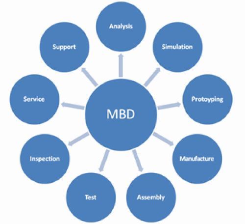
In today’s customer-driven design and manufacturing world, tolerances are ever-increasing as more and more functionality is being pressed into a shrinking product envelope. CAD models are now being annotated with more critical tolerances, beyond basic fit and clearance requirements, such as complex surface profiles. Since virtually all product development is now done in the CAD realm, the ensuing data and models are the perfect nominal standard to guide and inspect the entire manufacturing process. Model-based definition (MBD) is the term used to express closing the digital loop in the design, manufacturing and inspection process.
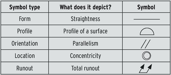
A necessary component of an MBD approach to part and mold design is 3D geometric dimensioning and tolerancing (GD&T), a universal symbolic and tolerancing language. In the MBD approach, the 3D CAD model is the authority, providing all the detailed product information for the product life cycle. The method moves the 3D CAD model from design to a manufacturing orientation, and allows software to automate and validate steps in simulation, manufacturing and inspection, thereby reducing human error.
Presentation vs. Representation Annotations
Since CAD’s beginning, the software architecture has supported the creation of 2D drawings. Later, GD&T annotations were added to the 2D documentation toolkit. It has only been recently that CAD programs have added 3D GD&T capabilities and that translation standards have supported CAD-to-CAD communication of that documentation. The tools are still evolving, so there are varying degrees of support from the CAD software programs.
One of the variations between CAD programs is the type of 3D GD&T provided. Two definition formats support MBD by eliminating conventional engineering drawings. Although both are labeled “3D annotation,” one format is purely for display, while the other feeds downstream applications.
Presentation is the display-only format for 3D GD&T. While the tolerancing may be associated to the model, the information is just text. There is no intelligence behind the 3D annotation. As a result, a human must interpret the GD&T information. The presentation format is similar to typing a mathematical equation in Microsoft Word. It conveys information, but the computer cannot use it in a calculation. In conversation, this approach is commonly referred to as “decorating the model.”
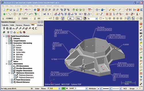
Representation is an intelligent application of 3D annotations. The GD&T feature controls represent data—not text—that is associated to the model and its features. This data can be interpreted and used by software applications.
What makes the effort of applying GD&T to 3D models worthwhile? As part of the MBD approach, it helps users leverage data throughout product development, cutting time from processes and improving them, while avoiding investment in 2D drawings. It can even be said that 3D GD&T data provides a form of “artificial intelligence” for manufacturing and inspection.
Model-Based GD&T for Inspection
GD&T defines quality requirements, and inspection then confirms these requirements are being met. An MBD implementation requires there is a GD&T representation and that inspection software can import data from the native CAD software. Or, when intelligent GD&T data is not available, users can add it to the 3D model in the inspection software.
In the MBD approach, 3D GD&T for inspection involves inspecting physical part measurements against a CAD model. This process can be dependent or independent of how or where tolerancing is defined on the CAD model.
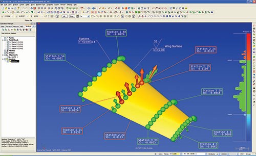
Some model-based metrology software for measurement, inspection, tool building and reverse engineering connects to and controls measuring devices such as scanners and laser trackers, as well as stationary and portable coordinate measuring machines (CMMs). It also accommodates both presentation and intelligent GD&T specs from 3D CAD models. Intelligent GD&T data is imported directly from supported software with the native 3D model and provides nominal dimensions. For presentation annotations, the engineer uses model-based metrology software to add GD&T specifications to the 3D model.
Importing information from a native CAD package as a 3D GD&T representation is a good example of MBD at work. The accuracy of the dataset is preserved. The same applies when GD&T display data (presentation) is imported directly (or via STEP translation) and entered into the inspection application. In both scenarios, there is no need to invest in creating or maintaining 2D drawings. Of course, 3D GD&T provides the most automated method of the above processes.
Closing the Loop
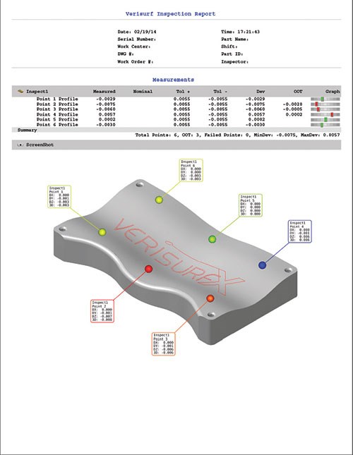
MBD with 3D GD&T closes the product development loop by eliminating ambiguity. In addition, it provides GD&T inspection feedback to engineers, who can use the data to determine root cause and either put processes under control or revise dimensioning and tolerance specifications.
To view a video on how to control all 3D scanning and probing measurement and data, visit http://short.moldmakingtechnology.com/vmeasure.
Related Content
Laser Welding Versus Micro Welding
The latest battle in finely detailed restoration/repair of mold materials.
Read MoreThink Safety: Eliminate Hazards Throughout the Shop
The tooling community is taking advantage of new products for safer mold shops and molding facilities.
Read MoreBreaking Down 3D Scanning in Moldmaking
Identifying 3D scanning requirements and implementing the appropriate technology.
Read MoreRead Next
How to Use Strategic Planning Tools, Data to Manage the Human Side of Business
Q&A with Marion Wells, MMT EAB member and founder of Human Asset Management.
Read MoreHow to Use Continuing Education to Remain Competitive in Moldmaking
Continued training helps moldmakers make tooling decisions and properly use the latest cutting tool to efficiently machine high-quality molds.
Read More
