3-D Laser Scanning Opens the Door to Inspection And Reverse Engineering for Moldmakers
Next-generation scanning technology precisely captures large and small molds.
Traditional techniques for making a mold require several time-consuming steps that can reduce how flexible and diversified a company can be. If the moldmaking process could be accelerated, moldmakers could build more tools for different products or variations of products in a fraction of the time. In these tough economic times, diversification can mean the difference between a business’s success or failure.
3-D Scanning
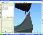
Using 3-D scanning technologies—such as a laser scanner mounted on a portable measuring arm—can significantly improve the efficiency of a moldmaking operation. The articulated arm moves similarly to a human arm, with ergonomic Zero-G counterbalance for one-handed operation from any position in the arm’s reach, above and below the midline. The scanner is used by moving it over, but not touching, various angles of a mold or part. Thousands of surface points are gathered in just seconds. The points, in the form of a 3-D point cloud, appear on the computer screen as you scan, and the software allows you to see the areas where you have and have not scanned.
This type of non-contact scanning system enables a very detailed examination of both geometric and surface features for any inspection or measurement task you can imagine. The arm-scanner configuration also allows for point data capture with contact probes when needed. Portability around the shop floor is a major benefit, and the scanning arm is available in measuring volumes ranging from 8 to 12 feet.
Point Clouds
For smaller molds, a laser scanned point cloud can be used to create an STL file in a point cloud processing software. The STL file is the standard format used by rapid prototyping systems to create either a stereolithography (SLA) or selective laser sintering (SLS) model. These models can be generated in various solid materials, which mimic traditional engineering polymers. For larger applications, the STL file can be used to generate a milling cutter path using any widely-available CAM software package.
When traditional hand measurement tools—such as calipers and micrometers—are used for defining part size, getting a truly accurate representation of the part is dependent on the operator’s skill. With a laser scanner, you can eliminate measurement inaccuracy due to operator error and achieve an accurate and complete representation of the part or mold. If a mistake is made by measuring the master part or mold with hand tools, the error likely will not be found until the finished product is complete. Laser scanning reduces total completion time by eliminating inaccuracy in first mold, so there is no need to repeat the moldmaking process.
Reverse Engineering
The ability to acquire an electronic copy of a part quickly and on location means there is no need to have the part in a specific place. You can go to the part rather than the part needing to come to you for reverse engineering. This is especially advantageous with automotive, aerospace and alternative power generation components where the size of a part or its location, in the case of wind turbines or solar arrays can make it impossible to simply box up the component and ship to your location.
Floor space costs money and storing master parts or molds can reduce the amount of free space that can be used to actively generate revenue. With a laser scanning system, the master mold no longer has to be stored forever. You can simply scan it and save the electronic representation of the mold to free up valuable storage area for other shop utilization. Also, in some applications where older parts are used, there may never have been a CAD model to begin with. After laser scanning a part, using several intermediate steps, a CAD model can produced, so that 2-D blueprints can be generated for fabrication.
Software and Point Clouds
A typical limitation with of point cloud software has been the overall number of points. However, the more points you can gather on a master part, the better the resolution of the point cloud, and this ultimately gives you a more accurate representation of the mold itself. Some point cloud software requires that you not collect too many points, or the software will be unable to handle the volume. Fortunately, this limitation has now been overcome with software programs, which have no restrictions on point cloud size.
Some master parts can have holes or surface imperfections that can be time-consuming to address with traditional methods. These can be fixed electronically by meshing the point cloud as triangular polygons, then applying surface smoothing and hole filling software tools. This fixes the model in a fraction of the time of fixing the master artifact, so that the finished mold quality is excellent.
It is also possible to verify an existing part’s geometry to the CAD models to see errors in the molding process from shrinkage, warping or wear over time. Simply scan the cavity, and compare the point cloud to the CAD model with visual indications of high or low spots. If your company has several molds that are supposed to be the same you could use the scanner to show graphically where the deviations are between the molds. This would make it far easier to modify the molds to ultimately produce more repeatable parts.
Summary
Today’s new generation of laser scanning tools are easier to use and more affordable than ever, putting them well within reach of most mold shops wishing to take advantage of modern technology to make them more efficient, effective and competitive.
Related Content
Three 3D Scanner Investment Considerations
Mold builders taking advantage of laser and software advancements for portable 3D measurement tools can reduce inspection and measurement times.
Read MoreIndiana Mold Builder Decatur Mold Offers a History of Grit and a Future of Innovation
Decatur Mold Tool and Engineering Inc. serves as a tooling tour guide, helping busy tooling managers reduce uncertainty, lighten workload.
Read MoreFour Micro Tooling Considerations
Issues involving gating, ejection, mold splits and direction of pull are of special concern when it comes to micro tooling.
Read MorePrecision Meets Innovation at IMTS 2024
After attending IMTS, it's clear that the integration of advanced technologies is ready to enhance precision, efficiency and automation in mold manufacturing processes. It’s a massive event, so here’s a glimpse of what the MMT team experienced firsthand.
Read MoreRead Next
Five-Axis Inspection for Moldmakers
Does five-axis inspection offer similar benefits in speed and accuracy for moldmaking operations?
Read MoreReasons to Use Fiber Lasers for Mold Cleaning
Fiber lasers offer a simplicity, speed, control and portability, minimizing mold cleaning risks.
Read MoreHow to Use Strategic Planning Tools, Data to Manage the Human Side of Business
Q&A with Marion Wells, MMT EAB member and founder of Human Asset Management.
Read More


