CAD/CAM Software Update Adds Features, Functions
CAM-Tool version 19.1 from CGS North America updates the software program to include more features and functions for high-accuracy mold and die machining.

Photo Credit: CAM-Tool
CAM-Tool from CGS North America, a CAD/CAM software designed for high-accuracy machining in the mold and die sector, is updating to version 19.1. Focused on increasing productivity and accuracy, this update includes several distinctive features and functions.
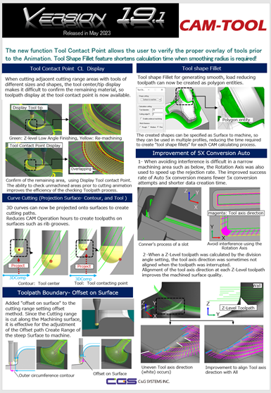
One function enables users to create tool shape fillet CAD entity. This generates a tool shape fillet as a polygon entity, which reduces CAM calculation time by using the shape in multiple profiles. By improving the use of shapes, CAM-Tool can save users significant amounts of time and increase efficiency, the company says.
Another addition is the function to display a list of tools used from the calculation process list. This feature streamlines the ability to share information between CAM operators and machine operators, improving communication and work coordination. Additionally, the tool list can be output to an external file in HTML format, helping keep track of the tools used and streamline the workflow.
CAM-Tool version 19.1 also includes a calculation that can recognize a hollow shape and remove an air-cut tool path. According to the company, this feature supports diversified machining geometries and reduces CAM operation hours, making the software more efficient and effective.
There is also a function to check for remaining material from overlapping paths — what the company says is a critical addition to CAM-Tool's capabilities. This function displays CL at the tool contact point, even when different types of tools are used together, such as barrel, lens or ball tools. This helps to confirm the remaining material when cutting adjacent cutting range areas with tools of different sizes and shapes.
Related Content
-
How to Manage Wall Thickness Changes in Your Mold Design
To ensure even filling and cooling, consider wall section transitions, corners and fillets, ribs and bosses, lip and rim designs and CAE flow simulation software.
-
How to Analyze and Optimize Cutting Conditions to Reduce Cycle Time
Plastic injection mold design and manufacturing company puts NC program optimization software module to the test. The results were surprising.
-
What is Scientific Maintenance? Part 2
Part two of this three-part series explains specific data that toolrooms must collect, analyze and use to truly advance to a scientific maintenance culture where you can measure real data and drive decisions.


