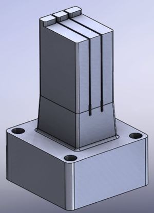
This tall insert for an inkjet cartridge represents one of many common applications for core shift analysis, as it may break due to melt-front induced deflection and fatigue. Images courtesy of 3D Shapes Inc.
Before completing any new mold, it is always best to understand what’s going on inside the cavity during molding to avoid problems such as core-shift. Today’s simulation tools can do just that. The right simulation can also help identify the root cause of existing problems faster and offer potentially less expensive tool modifications.
Moldflow’s core-shift analysis is a plastics simulation tool (finite element analysis) that mold designers can use to evaluate any mold insert, core pin or part insert that is in contact with the melt-front and affected by cavity pressure. Core-shift analysis works for tall cores, overmolded part inserts and even two-shot processes. Applications include cores for inkjet cartridges, syringe-like medical parts, as well as part inserts for medical devices and electronic connectors.
One of the most common applications is for tall mold inserts or core pins that may break due to melt-front induced deflection and fatigue. As an insert deflects due to pressure from the melt-front, it also changes the wall thickness of the plastic part and may affect melt-front advancement.
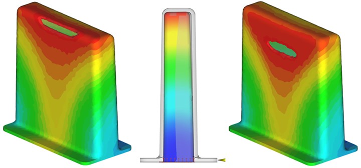
The left image is the melt-front’s last place to fill without accounting for core shift. The middle image shows a deflected core due to pressure on the insert. The right image is the melt-front’s last place to fill accounting for core shift. Images courtesy of 3D Shapes Inc.
Significant core movement and high stress will reduce the number of cycles to core failure. This is especially a concern for high cycle molds where core breakage can damage tooling and shut down production. A designer can use the stress output from a core-shift analysis to predict the number of cycles to failure. That information can be used to develop a mold maintenance plan that helps to get the maximum life out of the inserts prior to scheduled replacement.
Predicting the heat transfer from the melt-front to part insert components is another benefit of these simulations. It can be used to evaluate the bonding between the overmolded material and substrate or to determine if heat will damage any encased electronic components.
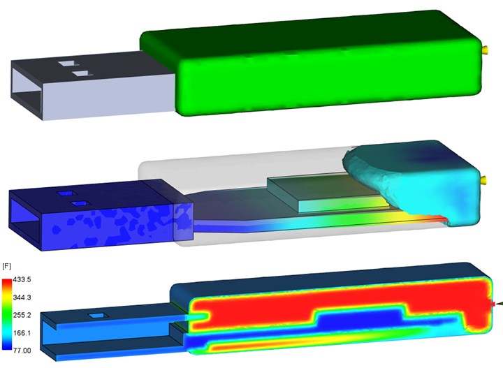
This overmolded USB drive image shows how the melt-front deflects the board. The bottom image shows how polymer heats up the circuit board and the chip.
Simulation tools for these types of analyses have improved greatly over the years making it faster and less costly to get results. In the past, analysis required a designer to run a plastics simulation separately and then apply the pressure field from the melt-front to a different mesh in a structural analysis package.
This approach required the analyst to determine at what time during filling he or she believed maximum deflection would occur. That is not always obvious with a complex flow path where the melt-front may surround the insert with varying pressure.
The most important step for achieving accurate results is to verify that the finite element mesh on the plastic part matches the mesh of the mold or part insert including draft.
A Better Methodology
The meshing and simulation capabilities within today’s plastics analysis software takes an integrated, streamlined approach, which is extremely reliable for clean CAD files. Analysts can bring solid models into the simulation software from virtually any CAD system.
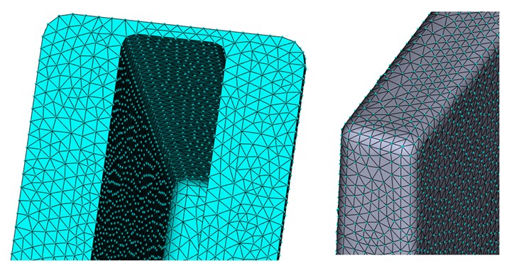
The nodes for each element on the plastic part (left) need to precisely match the location of nodes for each element of the core insert (right).
If a shop is using an outside simulation source, it is best if the mold designer provides the whole tool design and allows the analyst to extract the information required. Often, some minor CAD work is required to remove small details (text and logos) or to eliminate aspects of the core geometry that only increase the finite element mesh size and lengthen run times.
The most important step for achieving accurate results is to verify that the finite element mesh on the plastic part matches the mesh of the mold or part insert, including draft. For flat faces or minor mismatches, simulation software may offer reliable solutions. However, as the geometry gets more complex, especially with curvature and complex shapes, a good match of the mesh on both parts is required for accurate results.
After the part and insert is meshed, the analyst sets the molding process parameters for the simulation. Core-shift analysis results include part thickness changes, pressure, core deformation, resin freeze time, stresses on the insert and temperatures within a part insert. More specifically, analysis results will show deflection as the part fills and packs, the final displacement based on resin solidification and the resultant stress. If core deflection occurs, the software can also show the wall thickness changes in the plastic part.
Keep in mind that small changes can make big differences when it comes to increasing the number of cycles to failure for an insert. For example, modifications to inserts can eliminate problems associated with stress risers at sharp corners where failures often begin. Sometimes simple manufacturing changes to an insert can greatly increase the number of cycles to failure.
Simulation tools also allow designers to analyze alternate gate locations, different core materials and core geometry modifications during mold design. Additionally, designers can modify part geometry to reduce pressure or potentially change the resin to one that flows easier.
Since many tooling engineers may not be familiar with some of the jargon and technical aspects associated with finite element analysis, results provided with animations and concise, easily understood reporting can help to visualize the problem.
Core-shift analysis allows a mold builder to effectively see what’s going inside the tool during production. Defective plastic parts or broken cores are only symptoms of problems. Whether during the mold design phase or in production, analysis determines the root cause of these problems, finding solutions faster and with less expense.
3D Shapes Inc.
781-789-3380
Mark Howards, Founder, Mechanical Engineer, Autodesk Moldflow Certified Expert
Related Content
Revisiting Some Hot Runner Fundamentals
What exactly does a hot runner do? If you’ve been in the injection molding industry for any length of time, you might think the answer is obvious, but it is not.
Read MoreThe Ins and Outs of Hot Runner Temperature Control
A training checklist that explains the why and how of proper hot runner temperature control and system management.
Read MoreHow to Eliminate Chatter
Here are techniques commonly used to combat chatter and guidelines to establish a foundation for optimizing the moldmaking process.
Read MoreHow to Determine the Proper Vent Depth
Vent depth is critical to optimizing mold performance, so here is one approach to finding that elusive right number.
Read MoreRead Next
Designing Flow Leaders and Restrictors
Use simulation to control flow in your injection molds.
Read MoreAre You a Moldmaker Considering 3D Printing? Consider the 3D Printing Workshop at NPE2024
Presentations will cover 3D printing for mold tooling, material innovation, product development, bridge production and full-scale, high-volume additive manufacturing.
Read More

