Software Streamlines Complex CAD Design
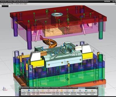
Understanding its success in the market, Caprock kept its focus on the design process and, in 2011, decided to upgrade its CAD tools to Solid Edge® software from Siemens PLM Software (Plano, TX).
Founded in 1983, Caprock Manufacturing Inc. (Lubbock, TX) is a privately held custom manufacturer of plastic injection molded products and assemblies for OEMs in the medical, utilities, transportation, energy and other industries. Vertically integrated services include moldmaking, product design, prototyping, and a wide range of finishing processes. Caprock’s enclosures business unit designs and manufactures casings for airline signage, water meters, electrical enclosures, durable medical equipment and other products.
Caprock excels in early supplier involvement, a process in which it partners with customers during the product design period to ensure manufacturability, quality and cost effectiveness while keeping tooling leadtime to a minimum, according to Joshua Walles, a senior project engineer with Caprock. This simplifies the design process and has proven to be much more efficient for all parties than the conventional customer approach of bringing the job out for bid only after the design is finalized and then finding manufacturability issues during the tooling process. Walles also points out that Caprock’s toolroom has a full complement of capabilities, enabling the company to perform everything from minor mold maintenance and repair to engineering changes—as well as building a complete mold.
Understanding its success in the market, Caprock kept its focus on the design process
and, in 2011, decided to upgrade its CAD tools to Solid Edge® software from Siemens PLM Software (Plano, TX). As a contract manufacturer, Caprock works with its customers to modify and redesign parts for product manufacturability. Most of the company’s engineers have no formal CAD training and are dual-tasked with project management duties. “Time is always a premium for us,” Walles states. “Our customers have come to ask and expect rapid response to their changing design needs. Engineering changes they want in a day. Major changes they want in a week. We have a history of being able to ‘get it done’ and pull off the ‘impossible’, not always, but regularly. And, since we have one CAD designer who doubles as our lead toolmaker, as the number of frequency and changes have gone up, that designer began to get overwhelmed.”
Caprock began looking at a number of software programs before discovering Solid Edge—and an unexpected bonus in synchronous technology Synchronous technology combines the speed and flexibility of direct modeling with precise control of dimension-driven design to provide the fastest, most flexible design experience possible, Walles says. Often, Caprock has only a paper drawing from its customers or sometimes a dumb solids file. Walles points out that bringing in a dumb solid with the previous program he used would be just the same as having a STEP equivalent. “I don’t have time to recreate all the features that require modification,” he states.
Editing CAD data with synchronous technology became a key interest point for Caprock. Walles points out that what used to take several hours to edit with the company’s previous program takes them less than an hour using Solid Edge. Plus, changes made by Caprock no longer require recreating the feature tree. “With synchronous technology, you just delete or modify the design feature and go,” says Walles. “It is simply a matter of selecting a surface/multiple surfaces and essentially pushing or pulling. Because that environment is not based on a feature tree where later items are based on former but one where features are independent of the whole, it reduces—and in most cases—eliminates calculation conflicts due to a dependency on another feature when one created later is modified.”
Walles also finds Solid Edge to be a very fluid and flexible design environment and one where changes would be much easier to make than in Caprock’s existing CAD environments. “Its advanced direct editing capabilities seemed to far outreach its competitors,” he comments.
“Normally, editing a ‘native’ file type is easy in a system because that system knows how its own files were created and editing them falls within the rules of construction that the system normally uses. Since most systems use feature trees, when a universal file type like .stp or .iges is brought in and the feature tree has been lost, these systems do not know how to edit the files well because that information has been lost.
“On the other hand, Solid Edge is designed to recognize individual features by themselves, so editing a file does not require knowledge of the relationship between those features (a feature tree),” he adds. Solid Edge even takes this a step further by attempting to recognize design intent between isolated features and applying consistent rules so that modifications to that file become automatically uniform, Walles maintains. The user also has discretion to tell Solid Edge to ignore those relations and fully isolate the feature being modified. This type of modeling works the same on both native, synchronous, Solid Edge files as well as universal file types.
Caprock reports significant error reduction since moving to Solid Edge. “I need to draw as fast as I think,” Walles explains. “The number of mistakes is much, much less than it used to be. Over a period of a year, I might have 20 customer redesign projects and would have to start all over in about 10 of them using our previous software due to a combination of lack of familiarity and fighting with the design plan. With Solid Edge and synchronous technology, that rarely happens. We also are able to turn ‘corrected’ designs faster with our customers because we do not have to compete for the use of one person. We are able to directly edit a larger variety of files and are not as hindered by the need for a feature tree because of the way Solid Edge looks at CAD modeling.”
Additionally, switching to Switching to Solid Edge freed up one of Caprock's critical human resources to focus more on where his time is needed most, Walles adds, resulting in a more balanced workload and efficient workflow.
Walles advises that mold manufacturers look into the 3-D CAD industry. “The program you are using now may not be the one that is the best for your workflow,” he concludes. “Be open to the idea that there may be a better. Get demonstrations. Ask questions. Educate yourself. You never know what you’ll find. We were certainly pleasantly surprised.”
For More Information:
Caprock Manufacturing Inc. / (806) 745-6454
joshua@caprock-mfg.com / caprock-mfg.com
Related Content
How a Small Programming Change Cuts Cycle Time in Half
Overriding the CAM system when milling a series of lifter pockets helps to improve metal removal rate and increase feed rates.
Read MoreHow to Improve Your Current Efficiency Rate
An alternative approach to taking on more EDM-intensive work when technology and personnel investment is not an option.
Read MoreTips for Tackling Mold Design, Machining, Cutting Tool and Wear Challenges
Tips for tasks ranging from reducing risk in part design and taking advantage of five-axis machining to refining cutting tool performance and reducing wear with guiding and centering systems.
Read MoreTolerancing in Mold Design, Part 1: Understanding the Issues of Conventional Bilateral Tolerancing
Mold designers must understand the location, orientation and form limitations of conventional tolerancing before changing to another dimensioning system.
Read MoreRead Next
Five Benefits of Integrated CAD/CAM
Integrated CAD/CAM software that combines CAD, CAM, electrode design and CMM programming capabilities in one system can save you time and effort in the following five ways:
Read MoreHow to Use Continuing Education to Remain Competitive in Moldmaking
Continued training helps moldmakers make tooling decisions and properly use the latest cutting tool to efficiently machine high-quality molds.
Read MoreReasons to Use Fiber Lasers for Mold Cleaning
Fiber lasers offer a simplicity, speed, control and portability, minimizing mold cleaning risks.
Read More


