Software Advances Push Limits of Speed and Quality
Software for moldmaking continues to evolve as sophisticated features and capabilities are introduced, enabling mold manufacturers to produce the highest quality work in the most compressed leadtimes to date.
CAD/CAM, NC and mold flow simulation, 3-D direct modeling and support software for 3D printing/scanning are working in concert with advancements being made in cutting tools, high-speed machining and automation technologies to give moldmakers what they need to produce high quality work in compressed leadtimes. Some leading manufacturers and suppliers reveal common questions they are asked as they unveil the newest packages, features and capabilities.
Software Challenges
When it comes to the topic of CAD/CAM software and its benefits, moldmakers typically want to know how the software handles the creation of machine cutting paths and programming, according to Chris Corbell, Vice President of Marketing of CAD/CAM provider BobCAD-CAM (Clearwater, FL). “This is a vast subject that includes both automatic roughing and finishing of simple and complex surfaces, cavities and part files that can require up to five-axis machining,” Corbell says. “They ask, ‘Can CAD/CAM help me machine this mold? How do I do it? Lastly, if it can, how easy is it to learn and is there support or service that comes with the software?’ Toolpath is also a big subject because of all the variations of complexity that fall into moldmaking with CAD/CAM software, which leads to, ‘Is the automation that is available easy enough for someone to open a part model and setup material, tooling and then create the machine toolpath for the job in an organized manner?’”
Mary Shaw, Marketing Manager for CAD/CAM manufacturer Delcam North America (Windsor, ON), notes that moldmakers are interested interested in anything that can help them provide a better service to their customers since they know that will help them to win more business and become more profitable. “Developments that can shorten their delivery times and improve quality are always important but as the shortage of skilled labor continues in North America more emphasis will continue to be placed on automation,” she states. “Companies will look for systems that link design, manufacturing and inspection in a more efficient manner. This does not mean a fully integrated CAD and CAM program, but rather solutions that meet the individual needs in order to improve processes and increase productivity.”
At CGTech (Irvine, CA)—a manufacturer of CNC machining software—Marketing Communications Manager Bryan Jacobs sees the need for speed in questions he tackles. “Moldmakers are looking for specific ways to increase machining speed,” he notes. “That is actually much less simple than it sounds. They’re really looking for ways to reduce the overall time to produce a finished mold by having the mold come off the machine tool with little or no post-machining finishing work. That means dramatically larger NC program files with very small step-over to produce extremely smooth finish machined surfaces.”
Jeff Jaje, Marketing and Business Development Manager for Sescoi USA (Southfield, MI)—a CAD/CAM, ERP and job management systems supplier—shares the question he is most commonly asked: “How can we mill the components faster and more efficiently?”
Efficiency is also on the minds of 3D geometry-based engineering software manufacturer Kubotek USA Inc.’s (Marlborough, MA) customers. VP of Marketing Scott Sweeney notes that the company’s customers want to know if Kubotek’s software can improve their productivity. “Moldmakers are slammed with business and any productivity gains they can get will allow them to get more work out the door,” he notes.
Efficiency and finish are top concerns of CAD/CAM provider Mastercam/CNC Software Inc. (Tolland, CT) customers. According to Marketing Director Ben Mund, most moldmakers want to see the best possible toolpath motion with as little “wasted” movement as possible and efficient use of their tooling. “They also always want the smoothest possible finish directly off the machine to avoid any time and labor-intensive handwork,” he says.
Randy Nash, President of CAD/CAM provider CGS North America Inc. (Oldcastle, ON) notes that moldmakers want to know how they can remove more labor from the CAD/CAM process to shorten the moldmaking process and how can they cut back on the total costs of perishable tooling?
Chuck Mathews, Executive Vice-President of CAM developer/supplier DP Technology Corp. (Camarillo, CA), notes that the company sees more requests from programmers than they do questions, and the most common request the company sees from moldmakers is to help them find ways to program their parts faster and more efficiently— which ultimately enables them to get their molds to the market quicker. “Their requests are most commonly driven by newer machine tools, controls and computer hardware—along with the fact that molds are becoming increasingly complex—all of which requires us to continually update our software in order to keep pace.” Mathews elaborates. “The requests that stand out most are for shorter toolpath calculation times, faster simulation and verification and more efficient toolpath cutting—in other words, shorter machining time.”
Justin Hendrickson, Product Manager, for SpaceClaim (Concord, MA)—a manufacturer of 3D Direct Modeling solutions for rapid concept design and geometry manipulation—notes that moldmakers typically ask questions like: What file formats do you import? Can you edit these files when they come in? How easy is it to create and restructure assemblies? “In today’s CAD/CAM environment, moldmakers are given models in all different formats and expected to work with them with ease,” Hendrickson says. “It is cost prohibitive to own a seat of every major CAD system and maintain proficiency with each. A single direct editing system makes it easy to import, edit, and repair geometry from different sources. In addition, direct modeling allows for more flexible assembly design that better matches the way a moldmaker splits and restructures parts to handle multiple pull directions and other mold features.”
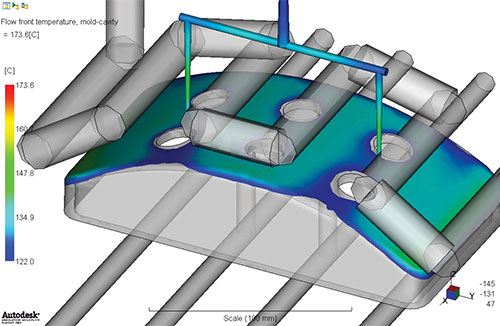
On the simulation software side, Hanno van Raalte, Product Manager – Simulation and Material Science for Autodesk (Waltham, MA)—a provider of 3D design and engineering software—notes that moldmakers want to know if the company’s simulation Moldflow can help make the right technology choices when it comes to the new cooling methods that reduce cost and cycle time while increasing quality of the plastic product (use of aluminum for production tools, local temperature controls through heating elements, rapid heating and cooling technology, conformal cooling, etc.
Tim Lankisch, Director of Engineering at CAE Services Corp. (Batavia, IL)—a provider of Moldflow engineering services, notes the following questions are asked of the company by moldmakers: Where should we put the gates or hot drops, and how many should we have? Is my cooling design adequate? Do I need any Moldmax inserts? Do we need to put windage into the mold to counteract warpage?
Over at CAD/CAM developer Vero Software Ltd. (Wixom, MI), Richard Youhill, General Manager for the VISI brand, notes that the most frequent question he hears is not actually a software or technology question. “It is simply, ‘Do you know of a mold designer I could hire?’ The lack of skilled operators is an impediment to the growth of our customers and to our software sales. We know we could sell more if we could supply each software license with a trained operator. Equally, our customers could secure more work if they could complete it on schedule.
“The second question of, ‘What do you have that will help me be more productive’ is linked both to the sudden uptick in business for our customers and the scarcity of talent,” Youhill continues. “Rephrased it’s simply whether or not our software can help them produce more with the same level of resource.” Both of these questions drive the company’s software development direction, according to Youhill. “We must continue to build the knowledge of experienced designers into the product and make it so automated and easy to use that less skilled operators can be successful with it,” he affirms.
Similarly, John Barnes, Technical Sales Account Manager for Cimatron Technologies Inc. (Novi, MI)—a provider of toolmaking and NC programming software solutions—most commonly receives non-software related questions. “Our customers want to know how business is elsewhere,” he states. “And, what improved processes do we encounter when traveling the country? Every shop is looking for the competitive advantage and wants to be reassured that it is a good time to make an investment in technology that will provide substantial ROI.”
Advancements
Intelligent Toolpaths
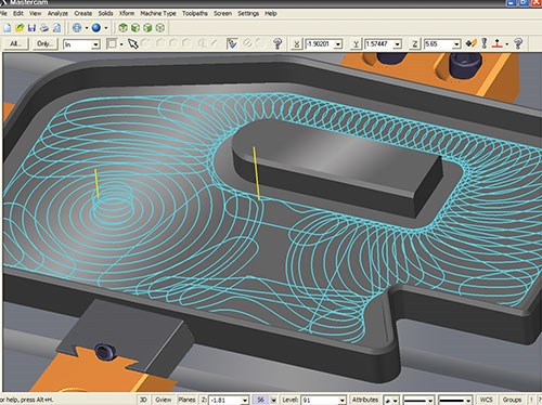
Steve Bertrand, Sales Director of Mastercam/CNC Software Inc. (Tolland, CT) believes intelligent toolpaths will be an area that grows by “leaps and bounds” in 2013. “Toolpaths that are aware of the remaining material, the machine, the tooling, and can make the most effective use of that information,” he elaborates. “We’ll continue to see more smart motion being generated that not only minimizes tool movement while maximizing finish, but also takes advantage of specific tooling and operates in a way that makes the tooling last longer while delivering a better finish.” To that end, the company has developed specialized settings for ISCAR Chatter Free tools using a method called High Efficiency Machining, or H.E.M. “Using this technique, this ensures the toolpath engages the material in a way that maximizes the tool’s capabilities—thus increases the efficiency as well as tool life,” Bertrand explains. “It all comes down to reducing costs while still maintaining, or even improving, the finish. We also continue to expand our popular dynamic milling toolpaths, which allows much faster cutting while actually extending tool life. And we also look forward to moldmakers using our ‘toolpath smoothing’ feature which creates a dramatically better finish directly off the machine.”
Shaw of Delcam adds that the company’s advancements in CAD/CAM that focus on increasing machine productivity will continue to be important to the industry. “Vortex, a new roughing strategy, is an example of how a productive machining strategy can increase machine efficiency,” she explains. “Like our other roughing strategies, Vortex toolpaths are calculated to give more efficient machining by following the shape of the part—keeping air moves to a minimum. Unlike other high-speed roughing techniques that aim to maintain a constant theoretical metal-removal rate, the Vortex strategy produces toolpaths with a controlled engagement angle for the complete operation. This maintains the optimum cutting conditions for the entire toolpath that would normally be possible only for the straight-line moves. As a result, the cutting time will be shorter, while cutting will be undertaken at a more consistent volume-removal rate and feed rate, so protecting the machine.”
Delcam has also developed a new technology called MachineDNA, which enables the CAM system to gather data from a specific machine to establish a performance baseline, and then uses that information to create an individualized tool path shaped by the machine’s condition and capabilities. “By learning and applying a machine’s own traits, different, yet effective toolpaths can result even though the same overall strategy (i.e. controlled engagement angle) is applied,” she states. “This brings a truly scientific approach to optimizing machining efficiency with a CAM system. It will replace the trial-and-error approach to programming by allowing right-first-time toolpaths to be generated on a consistent basis.”
Multi-Axis
Mastercam’s Mund says it is vital that CAD/CAM developments allow mold manufacturers to take advantage of multi-axis machines. “In certain cases, instead of machining using three-axis motion, customers want to use a five-axis tool motion with a shorter, more rigid tool. The users want the CAM system to determine the most efficient angle of attack. By using shorter tools, this minimizes vibration—which leads to better finish as well as access to areas that would require subsequent operations to complete the mold.”
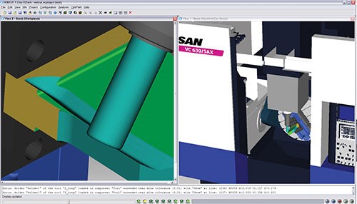
CGTech’s Jacobs adds that CAD/CAM companies are developing more specific methods for machining molds using five-axis machines to orient the tool for optimum cutting, as well as constantly developing faster path calculation algorithms. “We have been developing better ways to optimize feed rates for these complex cutting operations, especially using verification software to simulate the cutting contact and improve feed rates,” he comments. “Based on initial programmed feed rates, our optimization software automatically determines the optimum safe feed rate for each cut. Cycle time can be reduced significantly. Optimized feed rates also result in longer cutting tool life, fewer broken cutting tools and scrapped parts, better quality parts due to minimized cutter deflection, and a better finish on part surfaces and edges due to constant tool pressure.
Nash of CGS adds that moldmakers using SolidWorks are asking for a CAM add-in that in focuses on mold machining, not just general purpose. “Moldmakers are continuing their quest to add five-axis positional capabilities and five-axis simultaneous to automate the process, eliminate setups and cut with the shortest tool possible,” he says. “In addition, moldmakers want to automate the selection of the shortest tool possible for roughing and finishing and expect their CAM software can safely prepare the tool paths to deal with that.”
C&G Systems Japan is continuing to further develop CG CAM-TOOL to address all things required of a mold and die focused CAM software and work inside of SolidWorks, Nash adds. “Five-axis capabilities continue to improve to address all circumstances as they come up,” he comments. “Protrude Divide is a powerful addition to CAM-TOOL that can automatically create tool paths that are controlled by the different lengths of tools that you have at your disposal to eliminate the tedious effort the programmed has been involved in previous to this.”
Mathews of DP Technology adds the company is extensively focused on utilizing any form of parallelism in its software calculations, which enables the company to take full advantage of multicore, multi-threading microprocessors—especially when programming complex three- and five-axis parts. “ESPRIT also uses a multi-threaded stock automation engine, which allows users to start the part-program simulation at any time and at any point in the program,” Mathews states. “This eliminates the need to simulate all operations from the beginning or to save the results of previous simulations. Our users can instantaneously start a simulation with the stock that results from the completion of all previous operations.” Additionally, DP bases its toolpath calculations — and most importantly the roughing strategies — on the current stock state, which eliminates inefficient toolpath movement.
DP also is focusing on methods to incorporate more mold-specific CAD functionality into ESPRIT which allows programmers to modify CAD files to create geometric changes and additions required for manufacturing; and methods to include actual machine tools kinematics in the calculation of toolpath. “This new technology will overcome many limitations innate to all CAM systems, particularly in the field of five-axis machining,” Mathews says.
BobCAD- CAM just completed its latest full four- and five-axis software modules offering some very advanced machining capabilities, Corbell says. “In 2013 we are looking toward any additions that can be made in this area as well as the mill/turn possibilities that we have been getting asked for by our customers,” he states.
Automation/Efficiency
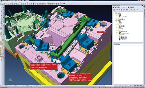
Youhill of Vero Software notes that the company likens its software development as “evolution” rather than “revolution”—as they are ongoing and build upon what’s gone before. “It’s important to remember that the vast majority of moldmakers do not design the component, choose how it’s designed or the format they receive the design, so the CAD/CAM system they use must accommodate all of these uncertainties—and allow them to build molds for increasingly complex components in a decreasing amount of time,” he emphasizes. “Therefore, we continue to focus on knowledge capture and automation, machining efficiency and thermal analysis of conformal cooling (3D cooling channels).”
Vero’s software developments take the shrinking workforce into consideration. “For instance, an experienced mold designer may know instinctively based upon on the component geometry whether or not the mold will fill correctly, but in the future the software must answer these questions,” Youhill says. “We have already automated several steps within the entire mold design and manufacturing process, but we know more is possible. For instance, with a completed mold design, an agreed set of machining rules and a populated tool database, the machining of mold plates is now completely automatic. The extraction and machining of electrodes is also fully automated.
“We consider machining efficiency in two parts,” Youhill continues. “First, how quickly can we calculate complex toolpaths from the model. While computing power has increased dramatically over the last 10 years, so have the complexity of the models our customers are working with.” The company has recently implemented Hive Machining, which allows complex calculations to be performed wherever there is capacity on networked computers. “For instance in machining, the application is smart enough to understand the sequence of machining events, such as roughing needs to be finished before semi-finishing,” he elaborates. “So the calculation of the roughing toolpath will be distributed across the network and completed before the semi-finishing process starts.”
Secondly, efficient toolpaths can significantly decrease machining time and increase tool life, Youhill notes. “Carefully controlling how a tool enters or exits part of the geometry and the consistency in which it removes material, is critical to surface finish, cycle time and tool wear.”
One shift in the mold world is the movement to conformal cooling, Youhill adds. “This is the production of 3D cooling channels built using rapid prototyping technology,” he states. “The benefit of this approach is the ability to create complex cooling circuits that can flow around an insert keeping a constant distance and therefore maintaining a constant temperature. This can reduce molding cycle times and prevent warpage.”
Jaje of Sescoi adds he believes CAD/CAM developments will provide more tools to increase the reliability and automate a lot of individual pieces to allow shop floor programming to move into a lights-out/unattended machining environment. “Additionally, faster and batch collision checking of the tool, holder, part and machine through batch processing will become more commonplace,” Jaje states. “There will be a greater reliance on the 3D stock model in not just the roughing stages of the part but also the finishing stages. Automated tool holder collision avoidance—including in five-axis—will allow people to mill more with shorter tools.”
For 2013, DP Technology has introduced ProfitMilling, a patent-pending, high-speed material-removal cycle that allows programmers to take a significantly deeper, faster and more efficient cut while reducing wear on the tool and machine, Mathews adds. The benefits of the ProfitMilling cycle are a reduction in machine-tool cycle times, increased tool life, decreased programing time, reduced energy consumption and significant productivity improvements—even with light and medium-duty machine tools, Mathews adds. “Test results have shown that it may reduce cycle time by 75 percent and increase tool life by 500 percent as compared to traditional concentric roughing strategies.”
Integration/Communication
Barnes of Cimatron notes that software must be relevant and seamless for the mold designer, moldmaker and mold manufacturing process. “I wish I could create a new term,” he comments. “To me, Cimatron isn't CAD/CAM in the original sense of the term. It is ‘CADMA’ (Computer Aided Design, Manufacturing and Assembly). We have taken out the slash—or ‘wall’ as I refer to it—between the design and manufacturing departments. Communication and intention has always been difficult to purvey from design to manufacturing. The term paperless has been a buzzword for many years now. When a company has a single software platform for quoting, design, manufacturing and assembly, then paperless becomes realistic. Without it, it's pretty tough, if not impossible. Breaking the design associativity by requiring translations between each stage will become a thing of the past in the future.”
In 2013, Cimatron’s number-one goal is to hand the life cycle of tooling from beginning to end with full associativity, Barnes maintains. “No other software should be required and you can operate with minimal paper,” he says. “In order to facilitate the communication mentioned above, we make use of PMI (product manufacturing information) in the model. This helps to communicate information—without paper drawings—via shop viewers or NC seats. PMI can be notes, attributes, dimensions, geometric dimensioning and tolerancing, etc. Design standards can also be derived from various colors that are passed to NC templates with intention such as clearance or shut-off that dictates different offset groups within a single cutter path. Parting edges can be kept razor sharp with new techniques. NC Templating is much closer to automated machining in Cimatron E11. Electrodes are nearly automated at every stage and posts out a G-Code file to be read directly into the CNC EDM sinker with locations and burn conditions. In summary, integration and automation go hand in hand to optimize efficiency and profit.”
At Kubotek, the company plans to continue to focus on interoperability between CAD file formats (the crux of Direct Modeling). “CAD and CAM will become even more integrated, and emphasis on managing design changes to increase profitability,” Marketing Communication Manager Andrea Giles says. “KeyCreator CAD has an integrated CAM program to allow 2½- and three-axis milling. When the CAD is updated the CAM is automatically updated.”
Plastic Flow and Cooling Simulation
CAE’s Lankisch sees simulation software providers making a big push to integrate their simulation products with CAD products in a seamless environment, which means that true 3D simulation will become more prevalent than it has been. “As has always been the case, simulation of the molding process will help moldmakers build better molds, more efficiently,” he says. “Overall, the mold manufacturing process will continue to become more robust and more efficient.”
Lankisch adds that the company is constantly evaluating and comparing new technologies, specifically those geared toward building finite element models for injection molding simulation.
Autodesk’s van Raalte notes that additive manufacturing processes like laser sintering are starting to make inroads in the tooling industry. “The technology allows for a great deal of design freedom and opens the door for broader use of conformal cooling, placing cooling channels where it’s most effective,” van Raalte says. “Autodesk has invested heavily in the simulation of new mold cooling processes over the last few years in preparation for the broader use of advance cooling technologies like rapid heating and cooling technologies, conformal cooling as well as the use of heating elements to temporary heat up critical areas in a mold. The ability to simulate these new processes will not only help our existing customers gain a competitive edge, but may also stimulate the broader adoption of these new technologies.”
3D Printer/Scanner Supporting Software
SpaceClaim’s Hendrickson notes that 3D printers and scanners are advancing quickly—as is the software that supports them. “Creating a CAD model from scan data is faster and easier than ever before,” Hendrickson comments. “As a result, creating molds from scanned parts or printing mold sections are likely to be increasingly common steps of mold design and creation. Mold designers will be able to better leverage existing parts and create more complex designs. In addition, model-based definition of parts is finally gaining traction. The latest ISO standards are defining an accepted format for semantic part manufacturing information in models. Moldmakers who are equipped to handle the changes will save time and money.”
SpaceClaim has partnered with 3D technology supplier Geomagic, Inc. (Morrisville, NC) to create a new approach to designing from scan data, Hendrickson of SpaceClaim says. “A new combined product, named Geomagic Spark, combines the best in direct modeling from SpaceClaim with Geomagic’s industry leading mesh creation and editing tools to create a single interface for going directly from a scanner to precise, editable geometry.”
SpaceClaim is a member of the ProSTEP iViP consortium involved in defining, implementing and benchmarking the latest ISO standards, Hendrickson adds. “We make sure that we can read PMI from many different industry sources as well as write it back out in the format that is most easily read by other vendors.”
Increased Sophistication
Mold manufacturers should take a close look at what software manufacturers and suppliers are introducing—and how it can improve efficiencies and operations on the shop floor. If the current features and enhancements are a sign of what is to come as the year progresses, chances are the offerings will become even more sophisticated—further reducing design times without sacrificing quality.
VIDEO: CAD/CAM Advancements Increase Machine Productivity
Related Content
How to Select a Mold Temperature Controller
White paper shares how cooling channel analysis, which collects maximum pressure drop, total flow rate and heat dissipation, eases the performance evaluation of mold temperature controllers.
Read MoreMold Design Review: The Complete Checklist
Gerardo (Jerry) Miranda III, former global tooling manager for Oakley sunglasses, reshares his complete mold design checklist, an essential part of the product time and cost-to-market process.
Read MoreHow to Improve Your Current Efficiency Rate
An alternative approach to taking on more EDM-intensive work when technology and personnel investment is not an option.
Read MoreWhat is Scientific Maintenance? Part 2
Part two of this three-part series explains specific data that toolrooms must collect, analyze and use to truly advance to a scientific maintenance culture where you can measure real data and drive decisions.
Read MoreRead Next
Choosing CAD Software For 3D Mold Design
The world of CAD offers many alternatives to shops that want to use the latest 3-D technology for their mold design. This article looks at the benefits of the various approaches and offers some tips on choosing the most appropriate one.
Read MoreReasons to Use Fiber Lasers for Mold Cleaning
Fiber lasers offer a simplicity, speed, control and portability, minimizing mold cleaning risks.
Read MoreHow to Use Strategic Planning Tools, Data to Manage the Human Side of Business
Q&A with Marion Wells, MMT EAB member and founder of Human Asset Management.
Read More
