No More Cooling Required
Moldmakers and molders can increase mold uptime using today’s cooling-free valve gate actuators.
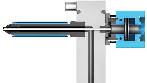
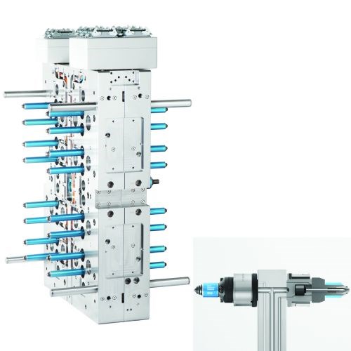
Valve gate hot runner technology produces better-quality plastic parts and faster cycle times by offering the most accurate gate control available. Valve gate systems are also an essential tool for automated injection molding because they enable faster mold start-ups, a wider processing window, and clean gates with no stringing or drooling of melt (see Figure 1).
Valve gate systems regulate the flow of material into the mold cavity using mechanical shut-off pins that allow the hot runner nozzle to open and close at the tip. The pin is moved into the open and close position using a valve gate actuator, which is available as an electric, hydraulic or pneumatic unit.
To help ensure the proper selection of a valve gate actuator, there are five common factors to consider.
1. Wear Resistance and Reliability
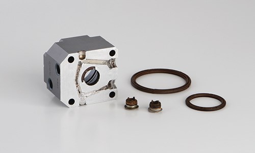
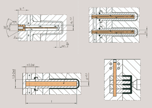
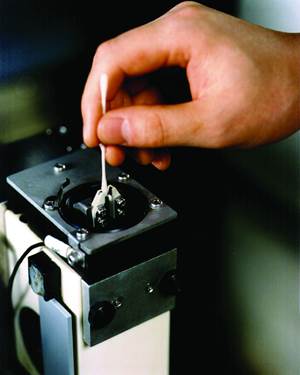
The same factor that allows injection molds to turn liquid plastic into a solid part is what breaks down most valve gate actuators: heat. Nozzles and manifolds are heated by electric heaters to temperatures ranging from 200 to 400°C (400 to 750°F). Other parts of the mold can be insulated from this heat and cooled using water. Although heat and friction are what ultimately damages most actuators, wear problems can often be traced back to a cooling-related issue (see Figure 2). For example, if a waterline clogs or fittings corrode because of impurities and minerals in the water, the mold will not function properly. But not all molds run on cooling water. Some applications experience mold temperatures as high as 200°C (400°F).
All mold components, including actuators, must be able to perform reliably for years at ambient mold temperature.
2. Valve Pin Movement and Accuracy
Different types of valve gate actuators generate different amounts of force, or the strength with which the valve pin closes. A certain amount of force is required to overcome melt pressure and to ensure the gate seals off or that the pin “comes home.” This is especially important when tough-flowing or high-viscosity materials are being molded.
Stroke, or how fast and how far the valve pin (or valve needle) can travel, also differs among valve gate methods. This can determine how much you control the melt flow with each shot, and valve gate response time in multi-cavity molds is important for achieving uniform and consistent cavity fill. Cascade and sequential cavity fill also requires highly accurate and repeatable actuation.
The height adjustment of the valve pin, or its position relative to the gate, also is a critical function. How easy is it to fine-tune your gate by moving the valve pin slightly up or down? This feature is no minor detail due to the effects of thermal expansion. It can also cost you hours of mold maintenance and setup time. Consider carefully how user-friendly an actuator unit is in this regard. It can make your life a lot easier in the long run.
3. Size
How big the actuator unit is relative to its performance also is important. Space inside any injection mold is valuable, so actuators should be as compact as possible.
In order to accommodate gates on contoured part surfaces, some manifold configurations require special angles, and smaller components offer design flexibility. Some single actuators can also drive multiple pins for compact close-pitch applications, such as those with multi-tip valve gate nozzles.
4. Mold Integration and Maintenance
How the valve gate actuator is integrated into the mold is another key factor to consider. Are the pistons machined directly into the top clamp plate? What happens when the mold (or tool) operates at mold temperatures of 100-200°C (200-400°F)?
The best mold components are modular, which means they can be easily and quickly removed, repaired, replaced, swapped, upgraded and/or reused. Actuators are no exception. An actuator should be a standalone unit, top-mounted onto the manifold or, even better, integrated directly into the nozzle body.
5. Cost Performance
What is better performance and reliability worth to you? All injection molding projects must strike a balance between short-term and long-term investments and gains. Quality plastic parts should produce a healthy return on investment. In the end, you usually get what you pay for. One way to cover your hot runner investment is to make sure your supplier offers a warranty that guarantees long-term performance.
Valve Gate Actuator Options
Now that some criteria for measuring the quality of a valve gate actuator have been established, let’s move onto the various actuator options.
Electric. Electric valve gate actuators are powered by electric servo or stepper motors. The technology involved in creating electric valve gates is relatively straightforward and widely available from suppliers of electric motors. The advantage of this power option is that it offers a certain degree of control when it comes to the pin’s position and motion. Some technology offers gate control that allows processors to adjust the flow rate out of the nozzle/gate at any time during the fill process to dampen or cushion sudden changes in the melt pressure. This function can have a subtle effect on part quality, but it is useful only in a very limited number of applications with non-shear-sensitive materials.
In the case of electric actuators of comparable size (to pneumatic and hydraulic), this control comes at the price of slow pin speeds and limited force. Compact electric actuators can only generate enough force for smaller pin and gate diameters. Variable pin speed is a feature also available in some advanced air-actuated hot runners, without the speed, temperature and force limitations of electric motors. High-speed pneumatic actuators offer larger pin diameters of 2.5-8.0 mm and gate diameters of 0.8–6.0 mm.
Another, more important concern related to electric actuators is their heat sensitivity. Electric valve gate actuators cannot handle the temperatures commonly reached inside injection molds. Generally, suppliers specify a maximum operating temperature of 130°C (265F°), but it is not recommended to run the electric motor at that temperature for any practical duration. Some suppliers specify a safe operating temperature of only 70°C (160°F). The fact is, at higher temperatures, electric motors begin to fail. This is why they are not more widely used.
One way to work around this temperature limitation is to mount the actuators externally, as far away from the mold heat as possible. One such method employs a plate that can actuate multiple cavities simultaneously. Mold design and maintenance for such systems is generally cumbersome, however. Also, this method cannot be used for cascade or sequential injection since the nozzles are attached to the same plate and cannot be individually controlled.
Another approach is to mount the electric motor on the top of the mold and mechanically transfer the movement to the pins using a belt drive (similar to what you find in a car). Again, this type of actuation is complex from a maintenance perspective and does not allow individual nozzle control for sequential or cascade fill.
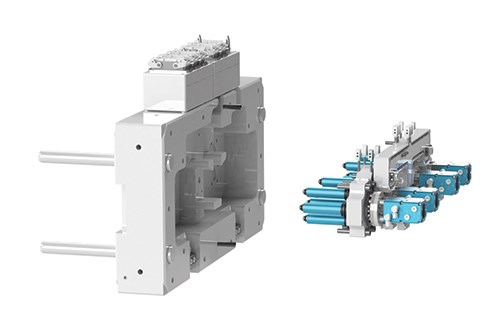
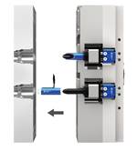
Hydraulic. Hydraulic valve gate actuators, or cylinders, operate using oil pressure. These systems offer the most force relative to their size. This is something to consider when you need to shear long glass fiber material at the gate, which is common in automotive applications. However, the amount of force required for these or other applications can also be achieved using some newer air-actuated cylinders (see Figure 3, page 23).
Dealing with hydraulics can be extremely messy, which eliminates it as a solution for medical molding applications. Lines can leak and then require bleeding whenever any work is performed on them.
Also, it takes time for hydraulic fluid temperature to reach equilibrium, and maintaining the fluid requires special equipment and maintenance. The added cost for high-pressure oil fittings, hydraulic hoses and hydraulic units is significant, and it’s not included in the mold price. In addition, hydraulic actuators require water cooling, and they are not very energy-efficient compared to electric and pneumatic actuation.
Pneumatic. Pneumatic valve gate actuators use compressed air to move a piston inside a cylinder into the open and closed positions. This is the most reliable and practical form of valve gate actuation, since pressurized air is a clean, low-cost and universally available medium. Most manufacturing facilities already have air compressors installed. Also, air offers an easy-to-connect, accurate control circuit with maximum flexibility for opening and closing an unlimited number of individual valve gate nozzles.
Conventional pneumatic valve gate actuators rely on air pressure, using a lubricated piston with elastomeric seals. For best results, it’s highly recommended that molders use nonlubricated air at 6-10 bar (85-145 psi). These systems perform well across all applications.
Traditional valve gates can be limiting, as they require the cylinder to remain cool to operate or to keep seals from breaking due to heat and friction. Even with cooling in place, elastomeric seals will wear out and need to be replaced, which leads to machine downtime and maintenance costs. Seals can also be damaged or destroyed if the correct start-up or shut-down procedures are not followed. More valuable machine time and energy is wasted waiting for cooling to run until the cylinders reach a safe temperature.
Another problem with cooling lines is corrosion and contamination. Pure distilled water is required, and cooling water quality must be maintained to ensure that it is pH neutral and contaminant-free so the systems will not stop functioning over time. Even potable tap water can cause problems in regions with high mineral content in the water supply. All of these issues can be mitigated through proper preventative maintenance, filters, additives and quality control.
Cooling-Free Solution
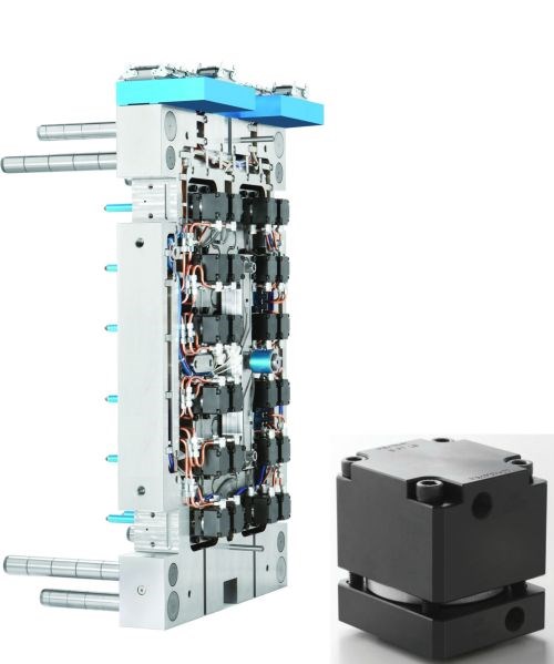
Increasingly, automotive, medical and electronics manufacturers are turning to high-temperature plastics such as PEEK, LCP, PSU, PEI and PPS for the special properties these materials offer. Processing them requires melt temperatures as high as 450°C (850°F) in the hot runner and mold temperatures higher than 200°C (400°F). Today’s cooling-free pneumatic valve gate hot runners offer precision performance in these hot conditions without cooling or wear (see Figure 4).
These cooling-free hot runners can offer all the advantages of air actuation without any of the issues associated with water cooling (hydraulic or electric) and are appropriate for all valve gate applications, including high-temperature and cleanroom molding. The actuators perform under extreme operating conditions while doing away with elastomeric seals, lubricants and cooling.
Cooling-free systems are characterized by their durability and ease of maintenance. No more production outages to replace seals. This particular feature makes cooling-free cylinders especially attractive for continuous operation in high-endurance tools running mass production. By contrast, cylinder maintenance for conventional valve gate actuators is complicated in high-temperature environments, especially in stack molds and tandem molds.
In addition, the instantaneous switching accuracy of cooling-free valve gate cylinders is in the millisecond range and much faster than that of electric actuators. Synchronicity across multiple mold cavities ensures that each part fills with absolute consistency. Their speed and reliability make cooling-free pneumatic actuators ideal for cascade injection and sequential valve gating, and they are also well-suited for sterile high-cavitation molds running in cleanroom settings because there is no abrasion of sealing material or contamination from lubricants.
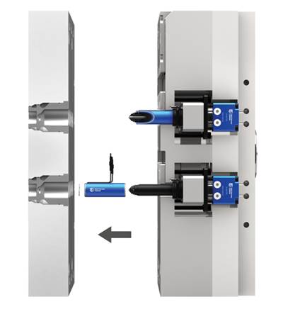
Internal valve gate technology places the valve gate actuator directly inside the nozzle. This way, no more external actuators are required and nozzles can be placed back to back for extremely compact stack mold layouts. This technology is available in many sizes, so all valve gate mold designs can benefit from its compact and robust features (see Figure 5, page 25).
The air and melt for these systems are supplied directly through the hot runner manifold, eliminating the need for external plumbing. No cooling is required because the actuator is made to operate at temperatures ranging to 400°C (750°F). If run to specification, the nozzles require zero preventative maintenance. The force and speed of actuation produced by these units exceeds those of conventional valve gate hot runners.
Hot runner technology like this can deliver improved performance and should help drive innovative mold design in the future.
MHS - Mold Hotrunner Solutions
Related Content
Fundamentals of Designing the Optimal Cooling System
The right mold components can help improve mold cooling and thereby produce higher-quality parts.
Read MoreMachining Center Spindles: What You Need to Know
Why and how to research spindle technology before purchasing a machining center.
Read MoreRevisiting Some Hot Runner Fundamentals
What exactly does a hot runner do? If you’ve been in the injection molding industry for any length of time, you might think the answer is obvious, but it is not.
Read MoreMaintaining a Wire EDM Machine
To achieve the ultimate capability and level of productivity from your wire EDM on a consistent, repeatable and reliable basis, regular maintenance is a required task.
Read MoreRead Next
It Pays to Take a Close Look at Your Hot Runner Warranty
As innovative companies push hot runner technology forward, a solid warranty can provide the insurance you need to switch to a better hot runner supplier.
Read MoreHow to Use Continuing Education to Remain Competitive in Moldmaking
Continued training helps moldmakers make tooling decisions and properly use the latest cutting tool to efficiently machine high-quality molds.
Read MoreHow to Use Strategic Planning Tools, Data to Manage the Human Side of Business
Q&A with Marion Wells, MMT EAB member and founder of Human Asset Management.
Read More
