Mold Engineering Done Right
How your business can translate sophisticated, up-front engineering into better parts and fewer problems.
The scenario: Precious time is ticking away in the development of an injection-molded plastic part, and trouble is brewing. You have identified a problem with the tooling system. Maybe it’s a cosmetic problem, or a dimensional issue. Worse yet, you might have a slide-by shut-off disaster because two pieces just won’t line up correctly.
By now, perhaps you’ve learned a difficult lesson: you could have avoided any of these problems long before you got this far.
Injection molds for plastic parts are complex works of art. The creative aspects of moldmaking require dedicated engineers who have the experience to blend imaginative design with part manufacturability. It requires an exceedingly precise process. Mold designers execute certain seemingly tedious, but critical tasks prior to performing the creative work that defines a product. In moldmaking, most problems occur at this legwork stage.
As a short-run injection molder for leading OEMs, Donnelly Custom Manufacturing (Alexandria, MN) continually strives to focus efforts where they will have the greatest impact on quality and productivity. In injection molding, rigorous dedication to engineering helps solve many injection molding problems—sometimes before they arise and steel is cut.
For example, a customer came to Donnelly to troubleshoot a problem. They were having voids in a thick-walled part, in which any void represented an unacceptable safety hazard. Additionally, the customer was experiencing a 50 percent fallout ratio.
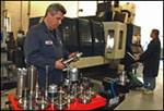
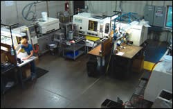
Donnelly was well organized to help solve the customer’s engineering-intensive problem. The company and its 220-plus people embrace best-in-practice technology, quality systems and training programs. Donnelly utilizes state-of-the-art equipment, information methodology and unrelenting manufacturing performance diagnostics. The company has more than 2,700 active molds and launches more than 200 molds each year. With Donnelly’s average mold generating less than $10,000 in annual molding sales, the company must ensure quality parts, fast and provide value-add services such as an innovative engineering services and design team.
For the challenging thick-walled part referred to above, Donnelly recommended several actions that resulted in greatly improved quality and increased product durability. First, in-mold transducers were installed to monitor and control variation of in-mold cavity pressure for each part during production.
Donnelly also purchased a North Star Imaging 80kV Microfocus X-ray machine to validate each part right after molding. This drastically reduced the time required to confirm that each part met acceptable standards. It became a real-time process—drastically reducing the production leadtimes and scrap.
Where to Begin
A well-designed finished tool starts with the design engineer. They generate an idea for a part to be produced and initiate the drawings. It might seem early, but it’s at this stage that you must start thinking about the manufacturing process, and thus, the mold design.
The first step is to determine gate loca-tion, where plastic enters the part. If it’s a cosmetic part, you don’t want plastic to enter near any visible, aesthetically impor-tant portion of the part. The gate can cause detectable flaws in the plastic. In addition, gate location determines the straightness, flatness and roundness of a part.
Next, determine the type of tool action required (e.g., hydraulic pull, cam or a lift). The action required is directly correlated to the functionality of the part. Chemical, heat and wear resistance considerations—as well as stress endurance and impact issues—also will dictate the type of action required for production and determine the functionality of the part.
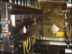
Concurrently, you need to be thinking about cooling the molded part in the tool. The primary question to ask is, “How can we get enough water in the part and have a repeatable process?” Proper water distribution—a challenging proposition—is critical to the cooling of the plastic. For example, a part may have a feature that requires a small metal blade, which would heat up and cause the steel to overheat. This ostensibly minor problem can cause major problems in the manufacturing process, significantly slowing production.
Identify the Common Problems
The first step in assessing a tool problem is quite simple, but also very effective: Place the tool into the molding process for trial-and-error testing. Once you witness the process, it becomes easy to rule out some probable causes of a problem and begin searching for the real issue.
Dovetailing to fix a part is oftentimes the first action someone will take to address a minor problem. However, dovetailing the part and maintaining part requirements, along with specifications, is difficult. Addressing the problem in the mold design, and making proper adjustments is always the best route to ensure quality parts and repeatable processes.
One of the easier problems to identify is a dimensional issue. Remaining steel-safe allows you to make dimensional adjustments on critical dimensions without welding. Also, a capability study is necessary to determine the final changes required to mold.
A cosmetic problem is typically process related. Changing how fast you inject the plastic into the mold or how long you hold the back-pressure is among many simple measures to remedy a cosmetic imperfection. If the problem persists, utilize the expertise of a process engineer.
Another problem is locating the proper place for gas to escape the cavity. When you’re injecting plastic into a cavity, you must design a release point for the gas. Typically, this is created with a pin, but pin placement is very important. Incorrect pin placement can cause other problems, such as a cosmetic flaw or improper form.
The hardest problems to assess are slide-by shut-offs. This happens when two pieces of metal sliding together are not in perfect alignment. There is no simple solution to this problem. The only remedy is through multiple trial-and-error tests. This involves checking the contact and making progressive adjustments to the steel.
How It All Works
Donnelly engineers are stationed on-site at customers’ locations to work closely with the OEMs’ design team. The engineers’ knowledge and insights are shared with manufacturing launch engineers on-site at Donnelly who ensure “good parts are delivered on time,” every time a new tool is launched. From there, highly trained molding-technicians ensure proper documentation exists to manufacture each specialized plastic part.
Donnelly’s on-site engineers have established relationships with customers and provide unique counsel and support to Donnelly’s customers around the world. In this type of relationship, both parties benefit. The customer benefits from knowing the engineer is capable and knows their standards and applications, and will deliver quality results. The on-site engineer benefits through their familiarization with the OEM’s product applications and business needs.
These relationships enable the customer/on-site engineer partnership to duplicate or move processes to other facilities world-wide. However, all is not complete in this partnership unless it also involves plant personnel, who will implement the output of the production process and any automation systems.
The greatest value to customers may not be in the upfront savings they enjoy, but in the enduring costs they avoid. By utilizing a single plastics manufacturer, customers avoid the cost of duplicating unique and expensive tooling. And they eliminate the learning curve and risks associated with manufacturing complex parts using multiple suppliers.
Related Content
It Starts With the Part: A Plastic Part Checklist Ensures Good Mold Design
All successful mold build projects start with examining the part to be molded to ensure it is moldable and will meet the customers' production objectives.
Read MoreHow to Manage Wall Thickness Changes in Your Mold Design
To ensure even filling and cooling, consider wall section transitions, corners and fillets, ribs and bosses, lip and rim designs and CAE flow simulation software.
Read MoreWhat is Scientific Maintenance? Part 2
Part two of this three-part series explains specific data that toolrooms must collect, analyze and use to truly advance to a scientific maintenance culture where you can measure real data and drive decisions.
Read MoreThree Good Reasons to Switch from Three- to Five-Axis Machining in Moldmaking
Five-axis machining technology is a great tool in the moldmaker toolbox.
Read MoreRead Next
Transforming a Modeling Tool Into a Collaborative Environment
Simultaneous product development and manufacturing represents a breakthrough in design team interaction—streamlining mold design.
Read MoreHow to Use Continuing Education to Remain Competitive in Moldmaking
Continued training helps moldmakers make tooling decisions and properly use the latest cutting tool to efficiently machine high-quality molds.
Read MoreAre You a Moldmaker Considering 3D Printing? Consider the 3D Printing Workshop at NPE2024
Presentations will cover 3D printing for mold tooling, material innovation, product development, bridge production and full-scale, high-volume additive manufacturing.
Read More
