Mold Cooling Options
A look at three options for integrating conformal cooling into a core or cavity with an emphasis on vacuum brazing.
Much has been written and discussed relative to the cooling of mold cavities. Most molders and moldmakers are at least aware of the benefits of placing as much heat removal technology into a mold core or cavity as possible. Simply drilling a hole into the bottom of a core for a closure and inserting a baffle or bubbler results in uneven heat. This heat must be lowered in the core to a temperature before the part can be safely ejected. This uneven heat results in a poorly cooled core, and a longer cooling time that is both wasteful and expensive.
As the technology has evolved for computer simulation of the injection molding process, molders are able to understand more of the science behind what is actually happening during the cooling process of the molding cycle. This becomes readily apparent when the molder understands what his product actually is: It is not simply the sale of a quality plastic part, but is actually the sale of his machine time. To state it as simply as possible, the product is cycle time. The more parts that can be produced to the customer’s specifications within a given period of time, the cost to produce each part is reduced.
Enter Conformal Cooling
Conformal cooling is a technique to get cooling lines as close to the surface of the molded part as possible. Moving the cooling lines closer to the part being molded, results in a shorter cycle time and a more uniform cooling of the molded part surface.
There are several options for integrating conformal cooling into a core or cavity.
1) Direct Metal Laser Sintering (DMLS): This is a process in which a core or cavity is built up in layers using a laser that builds the core or cavity up slice by slice. This is an ideal method when cores or cavities are a smaller size because the powdered metal is quite expensive.
2) Heat/Pressure: Another process to form internal cooling lines, which uses heat and pressure in a vacuum furnace to bond plates together. This process employs physics that occur when two pieces of steel are touching under heat, hydraulic pressure and vacuum. Essentially molecules jump the gap between the materials being joined and link together. The main limitation of this process is high cost and a joint that is not nearly as strong as the base materials being bonded.
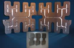
3) Plate Fusion Technology: This is a variation of the second process option. It still uses heat and vacuum to fuse two or more plates of steel together, but the difference is there is now a filler metal that is used between the plates—there is no filler metal in the previous bonding process. This process also reduces the cost for each part to be produced because it does not require centering the plates being fused to be located over a single hydraulic pressure source while in the furnace.
This technology was developed and refined by several producers of hot runner manifold systems for creating internal flow paths in hot runner manifold systems. It resulted in these manufacturers being able to place internal flow paths anywhere within any matrix of steel, in three dimensions while at the same time being able to withstand extremely high internal pressures.
Over time, customers of these hot runner manufacturers started to request that their cores and cavities be produced by the same method. The benefits of extremely high bond strength with the plate fusion process are helpful in conformally-cooled mold core and cavity construction. It results in cores and cavities that are able to easily resist water leaks over time by the external pressures created in the injection and cooling phases. It resists leaks because of the extremely high bond strength which is the result of this particular form of bonding versus others.
This process also allows the fusing of all the typical mold steels—420 stainless steel, H13, S7, P20, etc. These steels are also able to be fused to a copper-based material for a hybrid assembly if needed. After plate fusion is completed, the fused assembly can be annealed, heat treated, etc. as any other typical mold core or cavity.
This allows moldmakers to work with the steels they are used to. Grinding, milling, wire and ram EDM processes are performed just as they normally would be. The main difference is they are done with the fused assembly with the internal flow passages intact. All finishing machining is done after the fusion process is complete.
Case in Point
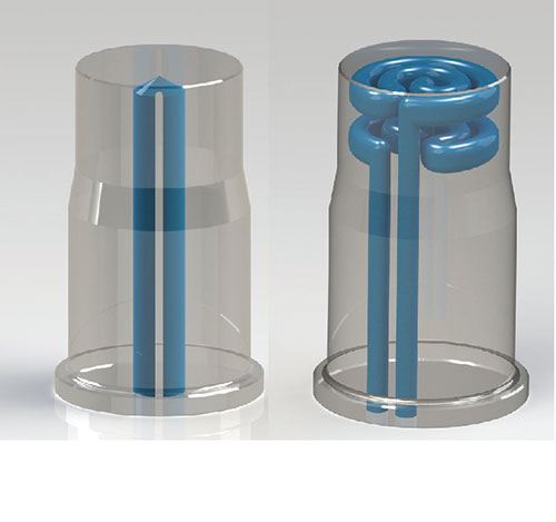
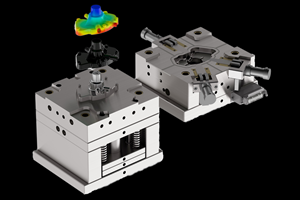
Figure 1 image below shows two typical examples of the mold cores used to produce a molded cap. One is cooled with a typical bubbler with the cooling coming up though the center of the core. The second example is a core with the exact same external dimensions, but with conformal cooling employed.
The example part being molded is a polypropylene molded cap, center gated with a pinpoint style hot runner system. An analysis was performed on both the bubbler and conformally-cooled core. The study included determining several factors that have an effect on the cycle time of the part as well as part quality.
Findings
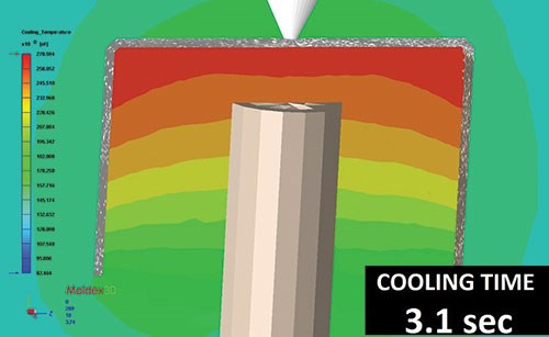
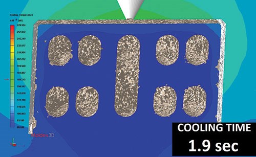
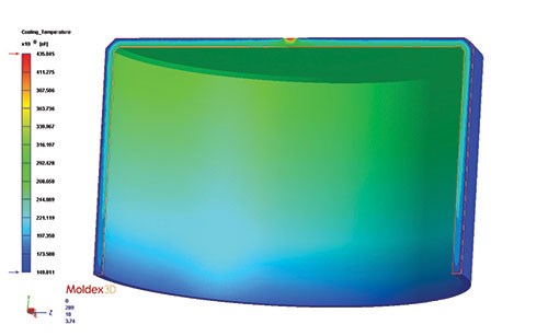
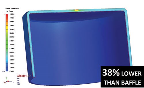
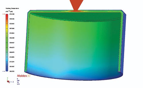
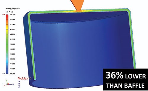
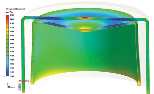
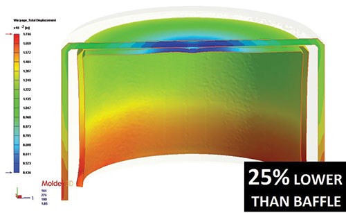
Bubbler versus conformal core with plate fusion (see Figures 2-5): Part Temperature at End of Packing Phase: Dropped from 165.7°F to 106.3°F., a 36 percent reduction on temperature. Part Temperature at End of Cooling Phase: Dropped from 149.8°F to 93.8°F., a 38 percent reduction on temperature. Mold (Core) Temperature at End of Cooling Phase: At the warmest place on the cores, the temperature dropped from 245.5°F to 118.5°F., which translated into a 39 percent reduction in cycle time. Also very interesting were the results on part warping. The total displacement warpage was reduced 25 percent on the conformally-cooled core with all effects included.
Summary
The use of conformal cooling is a win for everyone involved. The moldmaker sells more molds because he has a happy customer; the molder makes more parts per hour and the customer gets a better quality part at a lower cost. Using the best method for each particular application to produce the conformally-cooled cores and cavities will result in satisfied customers.
Related Content
How to Analyze and Optimize Cutting Conditions to Reduce Cycle Time
Plastic injection mold design and manufacturing company puts NC program optimization software module to the test. The results were surprising.
Read MoreTips for Tackling Mold Design, Machining, Cutting Tool and Wear Challenges
Tips for tasks ranging from reducing risk in part design and taking advantage of five-axis machining to refining cutting tool performance and reducing wear with guiding and centering systems.
Read MoreMold Design Review: The Complete Checklist
Gerardo (Jerry) Miranda III, former global tooling manager for Oakley sunglasses, reshares his complete mold design checklist, an essential part of the product time and cost-to-market process.
Read MoreWhat Is Scientific Maintenance? Part 1
Part one of this three-part series explains how to create a scientific maintenance plan based on a toolroom’s current data collection and usage.
Read MoreRead Next
Plate Fusing Technology For Designing and Building Manifolds
How plate fusing technology can benefit the mold designer/moldmaker.
Read MoreAre You a Moldmaker Considering 3D Printing? Consider the 3D Printing Workshop at NPE2024
Presentations will cover 3D printing for mold tooling, material innovation, product development, bridge production and full-scale, high-volume additive manufacturing.
Read MoreHow to Use Strategic Planning Tools, Data to Manage the Human Side of Business
Q&A with Marion Wells, MMT EAB member and founder of Human Asset Management.
Read More
