Plate Fusing Technology For Designing and Building Manifolds
How plate fusing technology can benefit the mold designer/moldmaker.
Advancements in technology for mold design and mold building have kept up with the technology for which the industry is producing molds. The technology to manufacture hot runner systems for injection molds also has been updated to keep up with the demands of these tools. One technology in the manufacturing of hot runner systems that has a great benefit to mold designers and moldmakers is plate fusing technology for manufacturing manifolds. Plate fusing technology enhances the traditional way of building manifolds—gundrilling flow channels and sealing flows with turn plugs.
Traditional Manifold Construction
Most hot runner manifolds are turn plug style manifolds where the manifold starts out as a solid piece of steel and straight flows are gundrilled into the block to create the flow channels. Turn plugs are then used to plug the drilled holes and to create the turns in the flows. Manifold manufactured in this fashion are limited to straight flows, 90-degree turns in flows, and typically contain steps between the flow channels and the turn plugs, which can create hold up areas for the material. A secondary operation to polish the manifold flows involves using a slurry to smooth the flow surfaces, but because this is a blind method, smooth flows without steps are not always guaranteed.
New Method for Manifold Building
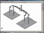
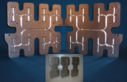
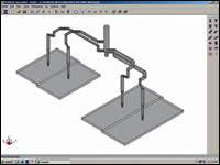
As the name suggests, plate fusing technology uses separate steel plates that are fused together to create a solid manifold. The process starts out with two or more plates. Flow channels are machined in the faces of the steel. These will become the internal surfaces of the manifold. These flows will be machined on a CNC mill with ball end mills to produce smooth, rounded flow channels with flowing radii at the transitions. The flows can vary in size and can travel between the levels of the plates to achieve the results that are required (see Figure 1).
Machining with ball end mills, combined with the repeatability of a CNC mill, eliminates the steps found in turn plug manifolds. The ability to CNC curved paths eliminates the 90-degree turns at flow transitions. After all of the machining is done, the plates go through a multi-step process in which the separate plates are fused together to form one complete manifold.
The plate preparation is analogous to making a sandwich, with a binder material sandwiched between the layers of steel. The final result is a single machined block with internal flows that can withstand the injection pressure flowing through the channels. The strength of a properly fused manifold is equal to that of a manifold made from a single block of steel.
There are many benefits in using a manifold manufactured with plate fusing technology. Using this technology in conjunction with a FEA on hot runner systems to help optimize it, mold designers can take advantage of this to change their way of designing molds for manifolds.
Number of Nozzles
Turn plug balanced manifolds typically come in 2, 4, 8, 16, 32, 64, etc. nozzle configurations. With plate fusing technology, a mold can be designed with a non-traditional number of drops and still be balanced. With the way flows are machined into the manifold, flow lengths and sizes can be varied to balance the flow and produce equal pressure at the gates.
Nozzle Locations
Plate fusing technology allows mold designers to place nozzles in virtually any location for gating. The length and diameters of the flows can travel between the different plates that make up the manifold. Internally, flows can cross one another on different levels to compensate for lengths and directions needed to reach a nozzle. Also, flows do not have to travel in straight lines to reach the nozzle.
For example, if you have one nozzle closer to the center of the manifold and one further away, to create flows of equal length to balance the manifold, the flows for the closer nozzle can travel back and forth and/or travel between levels in an isolated area to make up the straight line length of the further nozzle.
Family Molds
Designing family molds can be tricky in many cases because the part weights can be so different. This poses a challenge when designing a manifold to make sure parts are filled evenly. With the ability to create different size flow channels, balancing the manifold internally allows the mold to have common gate sizing, regardless of the part weights being molded. This helps the mold designers and builders to maintain common details in the mold.
Color Changes
With flows in the manifolds that are smooth and free of any hold up areas, color changes with manifolds made from plate fusing technology provide much quicker material changes when dealing with different color materials. The manifold can be designed with smoother traveling flows to help keep the material from getting trapped.
Design for Various Materials
Since flows are machined into the manifold using ball end mills, the diameter of the flows can be customized for specific materials. For harder to fill, glass-filled resins, larger flows can be machined. For LCP, small diameter flows can be machined into the manifold to produce the shear stresses needed.
Other Benefits
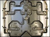
Another advantage of using a mani-fold manufactured using plate fusing technology is that it will be a hardened manifold as a result of the process the steel goes through. Also, since the manifold will be one piece when completed, there are no parts—such as turn plugs and screws—of which to keep track. The shape and size of the manifold is only limited to mold base size. Figure 2 shows an example of a completed two-shot plate fusion manifold system housed in its hot half plates.
Final Thoughts
Advancements are occurring on a regular basis in the injection molding industry. Not only are mold designers and mold builders implementing these new ideas, vendors such as hot runner manifold suppliers also are getting into the act. With technology such as plate fusing technology to manufacture manifolds, mold designers are able to expand their design envelope when trying to incorporate manifolds into mold designs.
Related Content
Revisiting Some Hot Runner Fundamentals
What exactly does a hot runner do? If you’ve been in the injection molding industry for any length of time, you might think the answer is obvious, but it is not.
Read MoreIt Starts With the Part: A Plastic Part Checklist Ensures Good Mold Design
All successful mold build projects start with examining the part to be molded to ensure it is moldable and will meet the customers' production objectives.
Read MoreMaintaining a Wire EDM Machine
To achieve the ultimate capability and level of productivity from your wire EDM on a consistent, repeatable and reliable basis, regular maintenance is a required task.
Read MoreMachine Hammer Peening Automates Mold Polishing
A polishing automation solution eliminates hand work, accelerates milling operations and controls surface geometries.
Read MoreRead Next
FEA of Hot Runners to Optimize Mold Design
Optimization of a mold design with a hot runner system can be done with CAE simulations.
Read MoreReasons to Use Fiber Lasers for Mold Cleaning
Fiber lasers offer a simplicity, speed, control and portability, minimizing mold cleaning risks.
Read MoreHow to Use Continuing Education to Remain Competitive in Moldmaking
Continued training helps moldmakers make tooling decisions and properly use the latest cutting tool to efficiently machine high-quality molds.
Read More
