Maximizing Machine Tool Potential with CAM Software
Identifying specific items where CAM software can take advantage of machine capabilities to the benefit of the user and maximize exploitation of milling machine potential.
Have you even read articles or attended lectures where an opening statement indicates that interactions of machine tools, software, and tooling dictate the success of a manufacturing process? In these cases, what specific information has followed to substantiate the well-worn thesis? The intention of this article is to go beyond general statements and to identify specific items where CAM software can take advantage of machine capabilities to the benefit of the user.
How Well Does Your CAM System Know Your Postprocessor?
Many CAM software products produce toolpath process data and write neutral-formatted output files, like APT CL data. An external postprocessor program then translates the neutral data to a specific machine tool focusing on machine tool kinematics and controller syntax information. This traditional process has certainly been successfully applied. However, the disjoint between the toolpath planning and postprocessing steps means that the postprocessor does not access certain information that can take advantage of the machine’s capabilities. Likewise, the CAM program often is separated from the details of the destination machine tool. The benefit of an integrated postprocessor technology is more dramatic in multi-axis applications.
Description of Local Programming Coordinate System
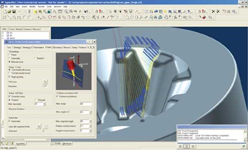
One example of additional information that can be passed from CAM to postprocessor to help machine performance is a description of local programming coordinate system. Most CAM systems operate on simple geometry on arbitrary orientations (such a holes, pockets and engraved lettering) by defining a local coordinate system or frame, and programming occurs in this orientation. The postprocessor makes necessary adjustments so the postprocessed machining instructions are transformed relative to a defined part origin and reference on the machine tool. Does your postprocessor know both the part setup coordinate system (NCS) and the local programming coordinate system (frame)? For many machine controllers, this information can be used to allow 2-D style programming with canned cycles and cutter compensation to be used for many operations occurring on tilted work planes.
Functionality Regarding Connections or Linking of Multi-Axis Drill Patterns
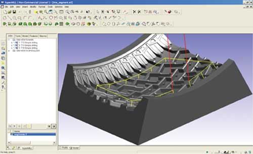
Another example is that the CAM software can have functionality regarding connections or linking of multi-axis drill patterns. If the CAM software knows that the machine tool control has tool center point management capability, then the linking paths between these drill sequences (usually made with moves to pre-defined safety locations) can use the knowledge of the control capability together with a synchronized and collision-checked linking path to keep the cutter close to the workpiece, and avoid both collisions and avoid added cycle time caused by continually moving to safety zones. By having this information available, there is higher process assurance and higher machine tool performance.
How Well Does Your CAM System Know Your Machine Tool?
Since machine tools have different capabilities due to size, speed, power, application intent, and other constraints and limitations, it is helpful for a CAM software system to have strategies that may apply in these different situations.
One end-user may have equipment to produce large molds as well as smaller, high-speed machines for the production of electrodes. So milling machines with significantly different capability may even reside within one plant.
While CAM software could focus on industry sub-elements, a broad-based solution that can productively address different styles is desired by the marketplace in which our example end-user could use one software product to achieve high performance on both applications and machine styles.
Five Axis Machining
Some of the clearly differentiating characteristics of machine tools are found in the class of five-axis machines. There are obvious distinctions, such as the kinematic layout—whether the rotary axes are with the cutter, or the part, or mixed; how the rotary axes are designed into the machine, and whether the axes are orthogonal to each other or at other angles.
Much is said and written about five-axis machining. This is a powerful machining concept with well-documented benefits to improve tooling, setups, surface finish and to allow access to complex geometries. But the complex dynamics of moving heavy masses (machine and part) suggest that full five-axis simultaneous solutions are not ideally suited for every application.
4+1 Machining
In many mold and die applications, users can get the tooling and setup benefits of multi-axis machining by seeking solutions with a locked pivot axis and active use of the rotary axis. This process is called 4+1 machining. In addition to facilitating improved dynamics, this process also takes advantage of the typically higher performing rotary (C) axis on a machine tool.
Mold components often have features with small radii that produce corners and edges on finished components. Historically, these features have been made with an additional EDM process operation. With five-axis machine tool technology, these features are often machined today. Small cutter diameters required to produce these features may be ineffective with long cutter stick-out lengths. The machining performance improves for small cutter diameters that have short cutter lengths with tapered thick shafts. A five-axis machine is generally used to accommodate thick-shaft tooling requirements.
3+2 Approach
Nonetheless, the cutter and machining performance is still improved by limiting the number of active axes. The 4+1 process described above can take advantage of a machine’s high-speed rotary axis. A process called multi-axis indexing seeks to simplify five-axis programs into segments of 3+2 machining, thereby further simplifying machine dynamics and cutter stability. A generalized 3+2 approach can lead to piecemeal set of solutions due to the fixed cutter orientation within a complex component. The multi-axis indexing process provides a process variation to allow the machine to manage multiple segments from one programming job and re-orient between them.
In some applications, like bumping the cutter up and down along the walls of a complex core or cavity, each individual toolpath stroke may have a different 3+2 solution than the previous and subsequent. A five-axis reorientation occurs while the cutter is in air transitioning between passes. The process can therefore machine an entire hard milling core or cavity with fixed angle machining in one program.
The machine tool performance is improved by using its multi-axis capability judiciously, yet applying the proven 3+2 process to ensure a high quality surface finish and longer cutter life.
How Well Does Your CAM Know Your CNC Control?
Advanced CAM software products have abilities not only to identify collisions prior to bringing them to a machine, but also avoid these collisions. When collisions are identified, there may be many alternative cutter orientations that can provide a non-interfering instruction. What are some of the rules that the software should apply? Are all non-interfering locations created equally? One paradigm used to solve this question is to ask a seasoned machinist. He would seek overall machine axis smoothness, avoid tight spaces, and avoid distant potential solutions by limiting the search to a controlled range.
Key Principles
The key principles to incorporate in the CAM software are to be able to bias collision avoidance moves based on the performance of the two rotary tables, to avoid potential locations that are very far from the baseline (interfering) solutions and to blend deviating instruction orientations with neighboring instructions to ensure smoothness.
The first point recognizes that machine tool rotary axes may have different specifications and the interference may best be resolved by moving the faster, more dynamic axis.
Avoiding potential locations that are far from the baseline solution will eliminate the potential for a very large angular deviation from neighboring points that would likely be accompanied by extra tool length requirements and reduced cutter dynamics.
Further, large orientation deviations would likely provide a sudden change in a rotary axis movement and may invoke acceleration requirements beyond the capability of the axis.
When the commanded NC instructions contain highly accelerating axis motion, the CNC control look-ahead functions will try to resolve these through internal compensations. The control will often depress feedrates (axis velocity) as a means also to reduce accelerations to achievable levels. Such a process may salvage marginal instructions, but will not lead to optimal machine tool performance.
CAM software solutions, especially in challenging cases of collision avoidance, must produce smooth instructions so that the control system does not invoke these override mechanisms. The intention is to create CAM software results that can be performed by the machine tool.
Summary
CAM software systems can positively impact the performance of the downstream processes in the machine tool and controller by knowing these systems and having mechanisms to co-exist with the capabilities of these process steps. Five-axis machining is not such a challenging process, and it is easier with a software system designed to attain five-axis performance.
Related Content
Tips for Tackling Mold Design, Machining, Cutting Tool and Wear Challenges
Tips for tasks ranging from reducing risk in part design and taking advantage of five-axis machining to refining cutting tool performance and reducing wear with guiding and centering systems.
Read MoreHow a Small Programming Change Cuts Cycle Time in Half
Overriding the CAM system when milling a series of lifter pockets helps to improve metal removal rate and increase feed rates.
Read MoreHow to Analyze and Optimize Cutting Conditions to Reduce Cycle Time
Plastic injection mold design and manufacturing company puts NC program optimization software module to the test. The results were surprising.
Read MoreThree Good Reasons to Switch from Three- to Five-Axis Machining in Moldmaking
Five-axis machining technology is a great tool in the moldmaker toolbox.
Read MoreRead Next
The Feature Technology Feature of CAD/CAM
CAM software should have forward looking features that allow you to work in a traditional programming approach and to step up into a more organized environment that includes storing process knowledge and corporate experiences.
Read MoreHow CAD/CAM Is Making a Programmer’s Job Easier
Arming yourself with the appropriate information will help you select the right software to help your shop work smarter not harder.
Read MoreReasons to Use Fiber Lasers for Mold Cleaning
Fiber lasers offer a simplicity, speed, control and portability, minimizing mold cleaning risks.
Read More
