Line Width vs. Depth Ratio in Laser Engraving
A laser does not produce 90-degree sidewalls. It requires a certain amount of draft in order to produce the required pattern.
A common challenge in laser engraving a mold is fulfilling a customer’s request to engrave type or a logo deeper than what the line width will allow. Engraving a registered or trademark symbol next to a logo in which the letters have very thin character line width, for example, prevents engraving as deep as the logo. This is because of the natural draft angle that is produced in laser engraving.
A laser is not a cutter that produces 90-degree sidewalls. It requires a certain amount of draft in order to produce the required pattern. Certain laser settings will help reduce the size of that draft angle, but none will completely eliminate the average 10-12 degrees needed for a neodymium yttrium aluminum garnet (Nd:YAG) laser or the average 6-8 degrees for a fiber laser. The draft will be necessary regardless of whether you are engraving into a hardened tool steel, aluminum or graphite (for electrodes).
The draft angle is required because the laser beam of light is stronger (hotter) in the center and weaker on the outside edges. The deeper an engraving must go into a mold component, the more passes with the laser are required and the greater the draft angle. If the depth of the engraving is deeper than the line width, the draft angles from both sidewalls will intersect at a point in the floor of the engraving. Once this occurs, no more depth can be achieved.
The simplest fix to allow for deeper engraving is to increase the line width of the characters or logo—if this is acceptable to the customer. A good rule of thumb is that the line width of the engraving should be equal to or greater than the depth of the engraving. You cannot engrave a 0.003-inch-wide character 0.010 inch deep and maintain a flat floor finish, but you can engrave a 0.003-inch-wide character 0.003 inch deep. However, increasing the line width of the engraving in the mold will also produce wider characters on the surface of the molded plastic part.
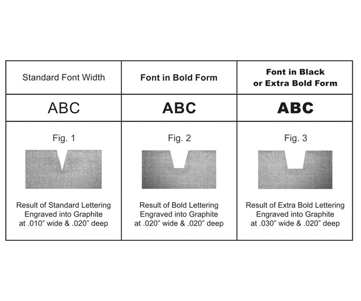 Photo Credit: High Tech Laser and Polishing
Figure 1 in the illustration above shows a cross-section of a piece of graphite that was laser-engraved to 0.020 inch with a standard font of a line width of 0.010 inch. Notice that the draft angle produces a pointed floor to the engraving, which would result in a pointed edged on the molded part. It also is impossible to reach the required depth if the rule of thumb explained above is not applied.
A bold font, meaning one that produces a wider character or logo, allows the laser to engrave a little deeper into the metal or graphite. Figure 2 shows a cross-section of a piece of graphite that was engraved to 0.020 inch with a 0.020-inch line width. Notice that the floor of the engraving is wider, so the surface of the molded plastic part will be a little flatter and easier to read.
Finally, a font or logo designed in an extra-bold form will allow the laser to engrave the deepest and produce the widest floor at the base or bottom of the engraving. Figure 3 shows a cross-section of a piece of graphite that was engraved to 0.020 inch with a 0.030-inch line width. Oftentimes, the logo or character font can be widened by offsetting or expanding it in the electronic file by 0.003-inch or more before engraving begins. If offsetting the artwork is not sufficient, then the engraving depth must be reduced in order to make it legible on the finished plastic part. In this case, a deeper engraving will not necessarily produce a more legible effect on a finished molded product.
This article was originally published 3/1/2017, updated and republished 6/17/2022
Related Content
Hands-on Workshop Teaches Mold Maintenance Process
Intensive workshop teaches the process of mold maintenance to help put an end to the firefighting culture of many toolrooms.
Read MoreMold Design Review: The Complete Checklist
Gerardo (Jerry) Miranda III, former global tooling manager for Oakley sunglasses, reshares his complete mold design checklist, an essential part of the product time and cost-to-market process.
Read MoreLaser Welding Versus Micro Welding
The latest battle in finely detailed restoration/repair of mold materials.
Read MoreWhat You Should Consider When Purchasing Modified P20 Steel
When buying P20 steels that have been modified, moldmakers must be aware of the variations and key issues that affect delivery, cost and lead times.
Read MoreRead Next
Laser Engraving/Marking: A Complement to EDM’ing and Milling
Laser technology may have a place in your mold build process when it comes to engraving and marking.
Read MoreReasons to Use Fiber Lasers for Mold Cleaning
Fiber lasers offer a simplicity, speed, control and portability, minimizing mold cleaning risks.
Read MoreHow to Use Strategic Planning Tools, Data to Manage the Human Side of Business
Q&A with Marion Wells, MMT EAB member and founder of Human Asset Management.
Read More
