Increasing Five-Axis Accuracy
Probing and five-axis auto-tuning can correct machine misalignments in minutes, not hours.
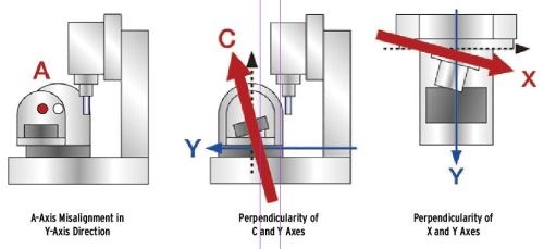
When moldmakers employ five-axis machining, it’s common for geometric errors to occur during the course of normal operation, and these errors can wreak havoc on finished-part quality. There are 13 geometric error types, including A-axis misalignment in the Y-axis direction and perpendicularity error on the C and Y axes. These errors are based on specific parameters, such as the strength, stress and dimensional deviations of the machine tool’s structure; thermal variations; cutting-force-induced errors; and tool wear.
For example, machines themselves can move with the general movement of operation, and this can sometimes cause the machine to no longer sit level on the shop floor. When this occurs, machine operators must perform on-site geometric tuning to compensate for any errors. Most moldmakers know the drill: a five-hour process that must be done approximately every 30 days. However, five-axis auto-tuning technology can perform these calibrations automatically in five to 15 minutes.
Manual Tuning
When a machine is installed, it’s typically leveled on the shop floor. After 30 days or so, the weight of the machine forces it to settle, however, and this can cause the axes to go out of square with each other, meaning the angles are out of 90-degree alignment and no longer perpendicular, which leads to geometric error (see Figure 1).
For angularity, the operator must then correct the “pitch-and-yaw” twist that develops in the machine. Yaw refers to a rotation in the Z axis, pitch is rotation in the Y axis, and roll is rotation in the X axis. When performed manually, tuning for rotary axis misalignment is a painstaking process involving many parameter measurements using a tooling ball, complex mathematical calculations and manual data entry. These tasks can take as long as five hours or more to complete, and require someone with leveling and alignment training. This process is also prone to some degree of human error.
When tuning for rotary axis misalignment, precision is an absolute necessity. Consider the following scenario: Five-axis is a three-dimensional world. On a five-axis machine, you must compensate for plus and minus error, up and down error, and side-to-side error. When you consider all the linear axes involved, there are a total of 16 different parameters (just through the X, Y and Z axes) that need to be set. Once they are set, the control software will reference each five-axis move, taking the error into account, to ensure that you are moving to the right place.
Because this is a three-dimensional environment, if any tuning adjustment is incorrect, it not only affects one axis, but all five axes. The pivot points on the rotary axis will be wrong, and the X-axis pitch and yaw are both tied to these parameters. You might proceed thinking you’re at 0/0 on all five axes, but perhaps the center line is off by 0.001 inch at zero on the table. If you’re making a 10-inch part, multiply this error by 10. You could literally miss the part with the drill.
Geometric error adds up very quickly. Manual tuning is a tricky business. Historically, taking a machine out of production for hours for tuning has been a necessary evil, but it’s a productivity killer that you no longer need to endure.
Five-Axis Auto-Tuning
Five-axis auto-tuning accomplishes exactly what the term suggests: It automatically tunes geometric error on five-axis machining centers, using a touch probe and tooling ball (datum sphere). The operator first places the tooling ball on the machining center’s table and the software identifies the number of points to be measured. The tolerance requirements of the finished parts will indicate how tightly the machine should be tuned. The more measurements taken, the more accurate the tuning and the longer the auto-tuning process.
Once all the measurement points have been identified, the operator indicates which tool number contains the measurement probe and pushes start, and the auto-tuning system will begin probing and measuring. The machine starts rotating the C axis and tilting A, for example, so now it’s on a compound plane and it probes at all the parameters indicated. All points are automatically probed and mathematical calculations are made. All the operator has to do is watch. There are no mistakes.
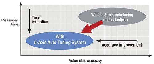
The entire process might take five to 15 minutes, and, because the process is automated, even a novice operator should be able to follow the procedure (see Figure 2). In this way, moldmakers can check and correct the machine anytime they need to, ensuring accuracy and productivity, and minimizing downtime.
The Probing Question
As outlined in the previous steps, five-axis auto-tuning requires that probing be installed in the tools. Many shops continue to resist using probes. When probes were in their infancy, there frequently were inaccuracies in their trigger mechanisms, machine tool interfaces and available software. However, in the past 10 years, probes have come a long way. Today, developments in probe trigger mechanisms make them as accurate as CMMs. They are also much more robust and affordable, and eliminate human error.
When used with standard machine tool probing software, a typical probe is fairly simple in functionality, although today’s PC-based controls offer the use of aftermarket software as well. Many probe manufacturers have developed their own software packages that can be loaded onto PC-based controls to take advantage of special applications not available from the machine tool manufacturer, such as an application for “manual/graphic” user interfaces for rapid part checks without the need to write an involved probing program. Users can utilize very complicated programming for part probing and customize to a much greater degree. Today’s extremely accurate probes match the accuracies of current machine tools, opening the door to new possibilities, like five-axis auto-tuning.
Related Content
Machining Center Spindles: What You Need to Know
Why and how to research spindle technology before purchasing a machining center.
Read MoreFive-Axis Vertical Mill Increases Mold Shop Capacity by Reducing Setups
Zero Tolerance now processes blocks — from squaring to waterline drilling to rough and finish milling — on a single five-axis CNC mill, reducing setups and moving blocks in/out of multiple machines without sacrificing accuracy and surface finish.
Read MoreTen Things You Need to Know about Circle Segment Milling
Considerations for evaluating if circle segment end mills or conical barrel cutters are right for your mold machining applications.
Read MoreFive-Axis Graphite Mill With Automation Debottlenecks Electrode Machining
Five-axis electrode cutting enabled Preferred Tool to EDM complex internal screw geometry on an insert that otherwise would have had to be outsourced.
Read MoreRead Next
Flexible High-Speed Mold Machining
Use this planning guide to identify the right double-column machining center to fit your mold machining needs.
Read MoreAre You a Moldmaker Considering 3D Printing? Consider the 3D Printing Workshop at NPE2024
Presentations will cover 3D printing for mold tooling, material innovation, product development, bridge production and full-scale, high-volume additive manufacturing.
Read MoreHow to Use Continuing Education to Remain Competitive in Moldmaking
Continued training helps moldmakers make tooling decisions and properly use the latest cutting tool to efficiently machine high-quality molds.
Read More
