In Search of the Infinite Processing Window
Side-action preload can yield zero core movement during injection and help molders achieve a robust molding process.
Embarrassment is a great teacher. In early 1995, after earning two engineering degrees, I ended up in the molding industry, selling common, spring-activated locking cylinders to mold builders. The key words here are spring and lock. I was having a tough time achieving customer satisfaction because, although the cylinders’ force was sufficient for holding loads on the side cores, customers often commented that the cores were flashing, and some claimed the cylinders were unlocking and backing up.
Of course, I knew that the cylinders were not unlocking and the locks were not backing up, but then what was happening? It seemed to all concerned that the customers must be doing something wrong or that something was moving somewhere in the system. After many visits to customers, application reviews and plenty of frustration, I knew something else must be causing the cores to flash, but I still couldn’t figure out what.
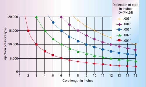
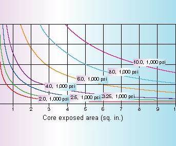
I finally sent a cylinder to a test lab and had it loaded to failure. The test results surprised me. After reviewing the data, I realized that I had simply failed to consider the physics associated with the steel molds and to use my training to question my own assumptions about the extent of steel compressibility. Steel is more compressible that we might imagine (see Figure 1).
Steel is Very Compressible in Molding
Steel is so compressible that even typical injection forces can negatively impact performance of steel molds. We know steel can bend and stretch because we see this happening when we work with bolts, but we never really think about it compressing. We know it does, but we still sometimes assume that the parts we are working with are too large to compress or that compression is insignificant. After all, when do we ever really crush something to failure? A block of steel always seems to just hold its own no matter what. And that is the challenge—the steel often holds, but in molding, holding is rarely enough.
Typical injection pressures of 10,000 to 20,000 psi can cause steel to not always maintain form or position. The steel may still hold the applied loads, but it might be compressing as it does. If this compression is not prevented or at least greatly minimized, the molding surfaces may not be in the proper position at the end of the shot. Gaps, variation in part geometry and flash will result.
Fighting for an Infinite Processing Window
So, if flex and bending were not enough to challenge us, we now have to consider steel compression in our quest to maximize our molding process windows. In his October 2014 Plastics Technology article “Flash-Free Molding.” Randy Kerkstra addresses the role of the tool in achieving a broad process window. He says, “My main focus is to have a robust process window, and this typically relies heavily on the tooling. I’ve been successful in focusing on the tool to address root causes to help achieve a broad processing window. While I agree that processing is the number-one tool for eliminating molding problems, every time you process around a root cause, your overall window becomes smaller.”
An “infinite” processing window relative to machine capability is preferred. A mold with zero dimensional change (zero movement) and thus zero part change up to maximum machine injection pressure would have an infinite processing window. Pressures and flow could be changed to fix other problems without worrying about the effects of pressure in the tool.
Often when a mold is in production, it must withstand more pressure than intended. Ideally, the mold builder would create a perfectly stiff mold (no flex or compression) that would have an infinite processing window. However, the mold builder is challenged with manufacturing very rigid molds, from non-ideal materials, that fit in the smallest possible space (smallest press size) and still produce perfect parts.
Unfortunately, mold stiffness is a challenge and often results in a tradeoff between mass and size. To combat bending and flex, more steel is added to the mold to increase stiffness and reduce movement under load, but this is counterproductive to making molds smaller. In other cases, compression is expected, so a mold core may be made longer than necessary (steel safe) and then cut back after tool sampling. There are numerous other methods for accommodating bending and flex, but they require process tweaking, which also entails adjustments to the core and limits to the processing window. To avoid this, there is an option not often considered: preload.
Preload: Bolts Offer a Frame of Reference
Someone who is unfamiliar with demanding loads on a joint interface or unfamiliar with torque might fasten joints together without it. If problems develop, he or she may simply decide to use successively larger bolts until the bolt is large enough to make the joint tight enough. This very-large-bolt design may be “good enough” for the loads expected, but may be insufficient if loads are unexpectedly increased. For this type of non-preloaded joint, any load on the bolt will cause some stretch, and the joint will always have some gap. Increasing bolt size to tackle this problem results in a much larger and heavier bolting system, which is limited depending on the allowable gap for the application. Most joints need zero gap, so this is problematic.
To those familiar with torque, the use of large bolts will seem counterproductive. Instead, smaller, torqued bolts are recommended. Below the torqued load, the joint will not separate and will provide constant position. A torqued (preloaded) bolt will not stretch, will maintain full contact and will remain tight.
Using a larger bolt with no torque interface can be made to work with some degree of success, however using a smaller bolt with a torqued interface is the preferred best practice.
Thus, the key to good mating of parts is preloading the bolts. Bolt size and torque is chosen to meet and exceed application parameters so parts stay in contact with zero movement. A properly designed bolted joint will have no movement under the planned loads, giving the joint a perfectly infinite operating window (zero movement) up to the preload amount. Can we do the same thing with moveable cores? Yes.
Preload Cores
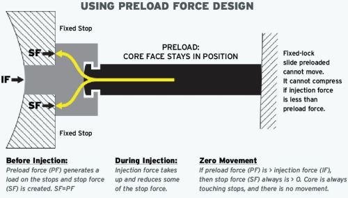
Just as applying torque to a bolt provides an infinite processing window for the bolted joint, so too does preloading mold steel into position on an injection mold. A core can be preloaded against a stop by applying a large force to the core and then capturing that force (or locking it in place) during the injection cycle. Rather than reacting to the force of the plastic and trying to resist it like a large finger-tight bolt, a preloading approach compresses the core, thus preventing movement, much like torque to a bolt.
Although the physics may seem a bit strange, the stop on the tool does resist the initial loading of the core with an equal and opposite force. As the plastic presses on the core, that load simply reduces the load on the stops without any movement. The stop loading and the plastic pressure always add up to a force equal to the preload force. The core does not move and the desired part shape is maintained regardless of the plastic pressure (see Figure 2).
While any method for applying a preload force to a core would work, the most common is using a hydraulic cylinder (or similar actuation means) and maintaining that force throughout the injection cycle by maintaining, capturing or locking it in place. Three methods include:
Hydraulic Maintaining Cylinder (hydraulics only): Applying a large force with hydraulics only can work, but it requires the hydraulic pressure to be maintained throughout the injection cycle, which is often not possible. It also often demands larger cylinders and a large hydraulic supply volume, both of which take up space and gallons per minute (gpm), which is not always available from the machine hydraulics to maintain cycle speed.
Cylinder and Heel Block (capture method): Another option is using a hydraulic cylinder to set and preload the core, and then capturing that force mechanically with a block of steel placed behind the core. This does not solve the large hydraulic volume requirement for preload and requires very accurate placement of the steel block after preload. It overcomes the need to maintain pressure during injection, and with correct timing on smaller cores, this method can be very effective in providing preload without much sacrifice in cycle speed.
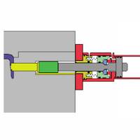
Preloading and Locking Cylinder (integrated method): A fully integrated approach is to use a force-intensifying (large force in a small size) and preloading locking cylinder. Such a system applies very large preloads in a small package to create a very rigid coupling between the core and the stop. This results in zero core movement during injection, and when properly sized, yields an infinite processing window (at least for movable cores).
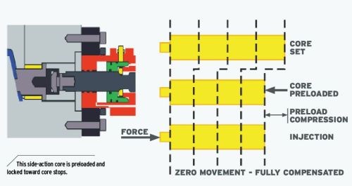
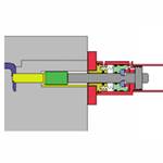
Figure 3 shows the core slide arrangement in the “set without preload” condition and in the “as preloaded” condition, with the indication that the back side of the core/slide is compressed toward the core face (dotted lines). As discussed in the previous section, during injection, the injection force (IF) is less than the preload force (PF), so the core face does not move.
Available force intensification and locking devices provide additional advantages for producing smaller and stiffer cores and molds. For example, mounting on the outside of the mold base reduces the size of the mold. Combined attributes allow for movement independent of mold opening/closing and for installation after the mold is in the press. The key value in these systems is the ability to preload cores toward the fixed stops and to provide an infinite processing window to moveable cores when and where possible.
Moving Forward
While any method of preload should provide an infinite processing window, it is critical to ensure that the amount of preload is sufficiently greater than any likely injection force, that preload is maintained during injection (independent of loss of hydraulics) and that core stops/shutoffs are sized to accommodate the preload force applied.
Additional considerations include ease of installation and adjustment for obtaining preload, hydraulic volume (which affects cycle speed), pressure requirements to obtain and maintain necessary preload, sensor operational limits and what is being sensed for feedback to press inputs, and available services for application reviews that include special considerations such as parting line mounts and opposing cores.
The advantages of preloaded cores are available to everyone as long as the basics of preload are understood and care is taken when sizing preload to the application.
Related Content
Standard Hot Runner Cable Range Extension
Hasco is now offering its H12251 cable in two different lengths and four different wiring standards.
Read MoreThe Ins and Outs of Hot Runner Temperature Control
A training checklist that explains the why and how of proper hot runner temperature control and system management.
Read MoreWorkpiece Clamping Systems Designed for Moldmakers
IMTS 2024: Modular and standardizing clamping system options optimize workpiece setups with high accuracy and high clamping force.
Read MoreRead Next
Mold Side-Actions: How, Why and When They Work
Understanding the effects of injection on the core, slide and associated components is critical to selecting the best side-action methods for a given application. This first of two articles will discuss the basic physics underlying all side-actions.
Read MoreMold Side-Actions: Applications Rule the Action
With a firm understanding of the effects of injection on the core, slide and associated components, this second of two articles will discuss emerging modular technologies which provide alternatives to the limited solutions previously available.
Read MoreAre You a Moldmaker Considering 3D Printing? Consider the 3D Printing Workshop at NPE2024
Presentations will cover 3D printing for mold tooling, material innovation, product development, bridge production and full-scale, high-volume additive manufacturing.
Read More
