Identifying Common Causes of Failure in Ejector Sleeves
Criteria that can be used in making ejector sleeves, which will minimize or eliminate failures as well as improve the performance and function of ejector sleeves and minimize maintenance.
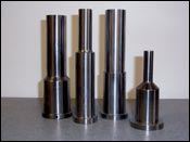
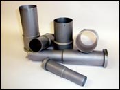
Basically, the function of an ejector sleeve in a mold is to eject either an entire finish molded piece part or apply ejection force to some portion of the molded piece part to assist with part ejection, in combination with other ejection features designed into the mold.
There are also cases where the ejector sleeve contributes to partial ejection or repositioning of the molded part, or the sleeve functions to “shut off” some feature for multi-shot molding. These later ejector sleeve applications function principally to support the multi-shot requirement and tend to be challenging as well as unique.
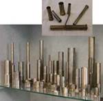
Sleeves can have actual molding detail on the inside and/or outside surface or function with shut off features or just have the basic “molding surface” on the very end of the sleeve, which in effect becomes the molded surface where the ejection force is applied. The mold design and piece part design determine the exact functionality, quantities and sizes of sleeves for a given mold and the relative piece part.
The following information is intended to aid in identifying common causes of failure as well as minimize maintenance with ejector sleeve assemblies, highlighting just some of the basic criteria that can be used in making ejector sleeves.
Tool steel is still the most common selected sleeve material used by mold-makers and designers, but aluminum bronze alloys are another option.
It is important to understand that adherence to specific procedures must be followed to yield predictable results when using tool steel materials for ejector sleeves. It is also important to understand that not all moldmakers, manufacturers of standard off-the-shelf sleeves or custom sleeve manufacturers neither agree with nor utilize the procedures suggested in this article.
Some sleeve manufacturers have taken the position that if they make the sleeves and the customer agrees to the manufacturer recommended material choice, running fits, clearances and coatings, a warranty for the sleeve life for an excess of three years in continuous running molds will be given (obviously this warranty would not be valid for component misuse or machine malfunction).
Tool Steel Sleeves
The basics of making ejector sleeves when using tool steel do require specific steps in manufacturing procedures as well as heat treatment steps that assure the maximum attainable life and performance possible. Even the maximum attainable life is often far less than expected with a heat treated and precision manufactured component.
Sleeve failures can present as “going out of round,” where the component measures to be “egg shaped” without evidence of any wear or metal loss. This condition leads to a combination of tightness in the component assembly while at the same time excess clearance to the component assembly, which may present as flash on the piece part. Galling is also a common problem, which is typically the result of hardness or metallurgical incompatibility, or incorrect running fit allowances or lack of lubrication in the assembly. These failures or conditions when using tool steel sleeves can best be categorized and attributable to not following required manufacturing procedures and where the development of out of round, size of shape changes relates to a condition that is defined by metallurgists as retained Austenite.
Retained austenite is a metallurgical structure or phase that occurs in the heat treatment of tool steel and is generally most notable and problematic in tubular parts, such as ejector sleeves. To minimize the presence or the effects of the retained austenite condition on the finish machined sleeves, a combination of machining and heat treatment processing needs to be followed.
The steps are as follows:
- Rough machine sleeves adding 1/16" oversize stock to all finish dimensional requirements.
- Then stress-relieve or anneal the sleeves.
- After the stress relieve process, further machine the components leaving stock allowance for finishing after heat treatment.
- At this point then heat treat the component as specified for the tool steel to final hardness.
- Now this is the important part, to minimize the potential for retained austenite, include without exception, a double draw and deep freeze process.
- Then finish machine the components to final dimensions. Anything less than using these six steps, leaves an open field for problems with the tool steel-based sleeve or the assembly.
Rotating Core Applications
In ejector sleeve applications with rotating cores, such as unscrewing molds for closures for packaging, not only is there potential lineal wear from the straight line ejector sleeve stroke, there is also the potential for rotational wear from unscrewing the part and then the rotary motion again to reposition thread orientation.
Venting the Assembly
Proper and adequate gas venting of the assembly is critical to sleeve performance. Without correct venting, molding gasses will accumulate in the fit diameters, between the pin and sleeve as well as the sleeve and outer bore the sleeve is fitted to. This accumulation of gases tightens fits, causes component misalignment and also reintroduces gas contaminants into the molding area during operation of the ejector sleeve. Proper and adequate venting eliminates these problems and also retains just enough gas residue, which acts as a lubricant for the moving assembly.
Vent Holes
Different than gas vents, having a vent hole in the side wall of the sleeve prevents a vacuum condition from interfering with part release at the completion of the ejector stroke. This is particularly important in ejector sleeve applications where there is not a through hole in the molded part at the sleeve location.
Orientation or Anti Rotation Features on Sleeves
Orientation or keying of sleeves is important so that at each mold assembly, the components are retained in the position or orientation that the components have worn in too. Some believe that free radial float of a sleeve actually increases the wear life of a sleeve because of the random position. This free float concept may sound practical, but makes analysis of component wear patterns of assemblies impossible and experience shows the practice actually leads to premature or faster wear of the assemblies.
Land Length of Sleeve Bore
The land length or lineal engaged portion of the inside of the ejector sleeve should be equal to the ejector sleeve stroke, plus one diameter of the pin that the sleeve runs on (ejector stroke + pin diameter = land length). Land lengths greater than this formula will not improve mold performance nor does it improve component life. Excessive land length also adds to the force required to activate ejectors. Land lengths less than this formula do not provide sufficient alignment/engagement of the ejector sleeve to the pin, leading to excessive wear and potential mold damage.
Nitride Treatment of Sleeve Wear Surfaces
Nitrides are generally applied to tool steel ejector sleeve surfaces to yield a hardness differential from contact areas matting to sleeve or wear surfaces of the sleeve. The real need, success and failure of nitride treated tool steel pins has been found to be nearly as predictable as the weather.
Ejector Sleeves Made Using Aluminum Bronze in Place of Tool Steel
While tool steel material is the more traditional material selected when making ejector sleeves, there are alternatives in the market that can avoid the shortcomings inherent with tool steel. Making sleeves using aluminum bronze alloys strategically eliminates all the heat treatment requirements, pre and post heat treatment machining, as well as the potential for retained austenite in tool steel. Remember these are in combination the primary cause for component size and shape change.
There also is the benefit of significantly reduced coefficients of friction between a bronze ejector sleeve and tool steel. The need for lubrication is nonexistent. Also, like hardness bronze or copper alloys can be run in combination without fear of galling. An aluminum bronze component can be run on a like hardness tool steel without fear of galling. Nitrides of any sort become unnecessary.
Moldmakers and molders using sleeves made using aluminum bronze have seen the performance improvements over the tool steel based products. That experience has led to entire plants initiating steps to switch over to aluminum bronze-based sleeves with plans to completely eliminate the use of tool steel-based ejector sleeves in any application in their facilities due to the extreme performance improvements.
![]()
Related Content
It Starts With the Part: A Plastic Part Checklist Ensures Good Mold Design
All successful mold build projects start with examining the part to be molded to ensure it is moldable and will meet the customers' production objectives.
Read MoreHow to Determine the Proper Vent Depth
Vent depth is critical to optimizing mold performance, so here is one approach to finding that elusive right number.
Read MoreLaser Welding Versus Micro Welding
The latest battle in finely detailed restoration/repair of mold materials.
Read MoreHow to Eliminate Chatter
Here are techniques commonly used to combat chatter and guidelines to establish a foundation for optimizing the moldmaking process.
Read MoreRead Next
Choosing the Right Aluminum Alloy for Production Injection Molds
Aluminum may be a better solution than steel after a thorough review of part design, tool design, quantity and type of unfilled, aluminum-friendly resin.
Read MoreDesign Criteria for Using Copper Alloys in Molds
The extent of copper alloy use, the success of its application and the life of the components are determined by the selected alloy in combination with the design of the application.
Read MoreHow to Use Continuing Education to Remain Competitive in Moldmaking
Continued training helps moldmakers make tooling decisions and properly use the latest cutting tool to efficiently machine high-quality molds.
Read More
