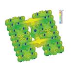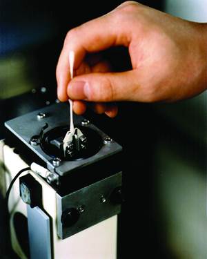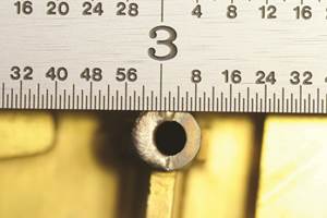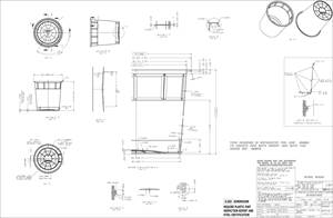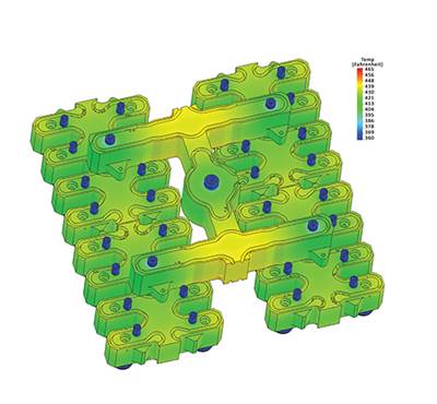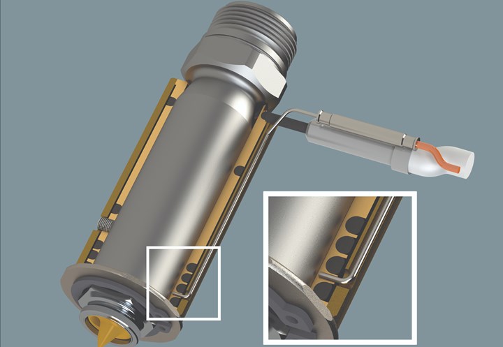
The tip of a thermocouple must be properly seated. Photo Credit: INCOE Corp.
The root cause of a recent part defect was reportedly the hot runner system delivering a melt that was too hot. The true root cause, however, was beyond my imagination. Here are the circumstances that prompted the molder to contact our technician.
The temperature controller zones setpoint temperature was 480oF, and the indicated actual temperature was 480oF and stable (no fluctuations). However, the material was stringing at the gate. The process technician, using a handheld device to measure the material purge temperature, reported it at 505oF. The only way to stop the stringing was a setpoint temperature of 455oF with an indicated actual temperature of 455oF, which was below the 465oF low end of the material. The technician then used a handheld device, and measured the purge temperature at 480oF.
Of note is the fact that a hot runner company did not supply the temperature controller and cables. Are you more intrigued now? Then read on.
Upon Further Investigation
The first consideration was whether the unseated thermocouples were falsely reading air instead of steel. This was not the case in this situation, but still a common problem and worth an inspection. After inspecting and confirming that all of the thermocouples (t/c) were properly seated to "read" the steel temperature and not the air, the technician replaced the hot runner temperature controller and used new power and t/c cables to test the mold. Now the setpoint temperature was 480oF, the actual temperature was 480oF, the purge temperature was 480oF and part stringing was eliminated. Although this solved the part problem, it did not reveal the root cause.
Although the molder had too much capital invested in the current temperature controllers and was reluctant to change, we pressed on with more in-depth investigation. First, we autotuned the existing temperature controller. But wait! The setpoint temperature was 480oF, the actual temperature (display) was 480oF and non-fluctuating, but the melt temperature was 505oF.
This is not a temperature controller autotuning problem. The hot runner system operated as expected with another temperature controller/cable setup, proving that it was not the hot runner system thermocouple placement/contact. It also proved that it was not the hot runner system junction box on the mold or the existing temperature controller. We deduced that it must be the thermocouple cable and/or poor plug/receptacle pin contact, which is a common issue. However, in this situation, the plug or receptacle was not the problem.
Next, we considered the cables. Often, the thermocouple wire will be a K-type instead of the required J-type, but again that was not the case here. However, what we did discover was that the molder was using copper wire.
Surprisingly (to me), the molder did not receive this discovery with gratitude. Instead, they expressed that they always use copper wire in place of thermocouple wire, that their mold builder who runs their tryouts also uses it, that they do not want the extra expense of the t/c cables, and that they have been doing this for years with no part issues. At this point, we were certain that the molder was unaware of the issues it was experiencing that were causing the part defects.
The bottom line is that you should not use cables with copper wire to monitor thermocouple feedback to the temperature controller for any molding application, especially those with "technical" parts and material.
The bottom line is that you should not use cables with copper wire to monitor thermocouple feedback to the temperature controller for any molding application, especially those with "technical" parts and material.
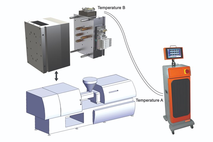
A diagram describing why you should not use cables with copper wire: air temperature at (within) mold electrical junction box (temperature B) = 100°F; air temperature at controller (temperature A) = 75°F; setpoint is 480°F.
No Copper Wire Cables
Here is an example to demonstrate why shops should not use copper wire cable to monitor thermocouple feedback to the temperature controller (see sidebar for definitions and diagram):
- Air temperature at (within) the mold electrical junction box (Temperature B): 100°F
- Air temperature at the controller (Temperature A): 75°F
- Setpoint: 480°F
- Using correctly-wired thermocouple (J-type or K-type) extension wire
If the hot end is 480°F, the Analog Input (AI) terminal block is 75ºF and the electromotive force (EMF) is 'seen' at the AI for any t/c type, then PV = 480°F - 75°F + 77°F = 482°F. When using t/c wired cable as required, the temperature at the mold electrical junction box adds a "zero" unknown error. Note: Temperature controllers require a fan-cooled enclosure.
With copper extension wire, the PV equation remains the same plus an "error" unknown to the operator (or the temperature controller). Since the PV equation does not change, neither does the temperature controller's indicated actual temperature. What does exist, but is not indicated, is the "error" that is the actual temperature at the tip of the t/c, which is the added "error" heat to the plastic.
If the hot end is 480°F, the AI terminal block is 75°F, and the EMF 'seen' at the AI is (still) then PV = 480°F - 75°F + 77°F = 482°F. However, when using copper wire, another junction is added that is not part of the temperature controller logic. The error is not visually indicated on the controller.
The t/c-copper junction is at 100°F (Temperature B): Temperature B (100°F) -Temperature A (75°F) = 25°F. The real actual temperature at the tip of the thermocouple is the real temperature of the melt at 505°F.
Again, the real actual temperature is 505°F because you cannot program the temperature controller with the cold junction and another junction (always a variable). The user has no way of knowing this and trusts the indicated/actual temperature readout on the controller as gospel. For instance, the material in this example is 25°F hotter than what is indicated on the temperature controller readout.
Also, the inside temperature of a mold junction electrical box mounted on the top side of a mold can experience temperatures well over 100°F, especially during the summer months in some areas. These temperatures will add and subtract from the unknown error relative to the time of the day and season, which may then impact the temperature within the shop at daytime or nighttime.
Related Content
Mold Design Review: The Complete Checklist
Gerardo (Jerry) Miranda III, former global tooling manager for Oakley sunglasses, reshares his complete mold design checklist, an essential part of the product time and cost-to-market process.
Read MoreMaintaining a Wire EDM Machine
To achieve the ultimate capability and level of productivity from your wire EDM on a consistent, repeatable and reliable basis, regular maintenance is a required task.
Read MoreLaser Welding Versus Micro Welding
The latest battle in finely detailed restoration/repair of mold materials.
Read MoreIt Starts With the Part: A Plastic Part Checklist Ensures Good Mold Design
All successful mold build projects start with examining the part to be molded to ensure it is moldable and will meet the customers' production objectives.
Read MoreRead Next
Reduce Part Failure with Melt Delivery Science
The best way to determine when naturally balanced, rheological managed and thermally balanced hot runner solutions are required as a single solution is to examine the science behind each approach.
Read MoreAre You a Moldmaker Considering 3D Printing? Consider the 3D Printing Workshop at NPE2024
Presentations will cover 3D printing for mold tooling, material innovation, product development, bridge production and full-scale, high-volume additive manufacturing.
Read MoreHow to Use Continuing Education to Remain Competitive in Moldmaking
Continued training helps moldmakers make tooling decisions and properly use the latest cutting tool to efficiently machine high-quality molds.
Read More

