Minimal Investment In New Tooling Tech Increases Productivity, Tool Life and the Bottom Line
Having a fundamental base of the facts makes it easier to detail how some of the latest innovations in cutting tool substrates, geometries and coatings can make it easier for one’s moldmaking process to go from fast to furious.
In the U.S. die and mold industry, staying ahead of the curve can be the difference between steady business and immensely lucrative business. There are several strategies one can employ to make their business more profitable, but few easier than utilizing new tooling technology to make what is good, even better. In this article, new developments in tooling technologies will be revealed and explained to help those in the business of moldmaking stay ahead of the proverbial curve.
Before getting ahead of the curve, it is important to have a solid base of the factual knowledge as it relates to cutting tool technology. The core components that make any cutting tool of lesser or greater quality are the substrate, cutting geometry and surface treatment. In terms of these components, there are certain features or characteristics that stand out with respect to the moldmaking process.
Substrate
What do we need to know about the substrate? Just grab your nearest carbide tool and start milling that hardened block of H13 or D2 material, right? If only it was that easy. As most moldmakers know, not all mold steels are created equal. In fact, if one has ever experienced the transition from P20 to hardened D2, then you know exactly what we are talking about here.
This is a critical point, because the same is true of carbide substrates. Carbide, by definition, can actually be classified under four different categories. These categories are shown in Chart 1.
| Chart 1 | |
| Carbide Classification | Grain Size (microns) |
| Micro-Grain Carbide | 1.0 ~ 1.3 |
| Sub Micro-Grain Carbide | 0.6 ~ 0.9 |
| Ultra-Fine Micro-Grain Carbide | 0.4 ~ 0.5 |
| Nano Series Micro-Grain Carbide | 0.1 ~ 0.3 |
| Carbide classification. Chart courtesy of OSG Tap & Die. | |
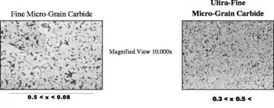
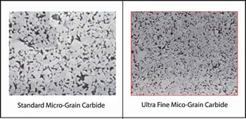
The smaller the grain size, the harder the carbide substrate will be and the more resistance it will have to wear (see Figure 1). Breaking down the substrate even more will reveal two key characteristics: (1) toughness and (2) hardness.
Toughness
The toughness of a substrate is defined by how much force (N/mm) can be applied radially to the substrate before it fractures. The common term used to illustrate this measurement is transverse rupture strength (TRS).
Hardness
Hardness is simply determined by how much of an impression can be made in a given material using a hardened-tipped object, when an exacting force is applied. The harder the material, the greater resistance it has to deformation.
TRS and hardness are both directly affected by the percentage of Cobalt present in the carbide substrate. Cobalt is the primary bonding element in carbide. Higher percentages in Cobalt will yield a substrate that is tougher (more TRS), yet less wear-resistant due to a decreased hardness. Inversely, when the Cobalt percentage is lowered, hardness and wear resistance increase while toughness is sacrificed.
Premium cutting tool manufacturers study and know the difference, and will often utilize a dozen different substrates to produce unique tooling designed for anything from hogging aluminum to high-speed milling in hardened die steels.
Geometry
The advent of new high-speed machine tool technology has brought about the necessity of more sophisticated tooling capable of sustaining stable performance at elevated spindle speeds and feedrates. The market of commodity carbide tooling has little or no place in today’s high-speed/hard milling industry. It is not to say there is no place for it, but the advanced machines currently on the market do not lend themselves to the carbide tooling that was designed 20 or even 10 years ago, for a market that has completely changed. The geometry of a tool in the realm of hard milling must be synonymous with rigidity and accuracy.
In terms of rigidity, the primary feature of any solid-round cutting tool is core diameter. The standard core diameter for an end mill is 50 percent of its diameter. However, for hard milling, greater rigidity is required; hence, a core diameter of 60 to 70 percent is used. While flute gullet space is sacrificed, the pay-off is a more rigid body with increased mass behind the cutting edge to sustain it in hardened material. Since the depth-of-cut rarely exceeds 10 percent of the tool’s diameter, gullet space is less of an issue.
Another term for accuracy, where it pertains to 3-D milling, is radius accuracy. The radius accuracy of the ball end mill dictates how much benching will be required when the cavity and core are completed. While premium ball end mills will be checked every 10 degrees for radius accuracy, commodity tools are frequently subjected to far less critical inspections. The result translates to part inaccuracies that lead to hours of unnecessary benching work.
Surface Treatments
The fundamental machining methods of high-speed machining and hard milling result in elevated and consistent heat generation. As a result, the standard physical vapor deposition treatments—such as a TiN or TiCN—are no longer advantageous. The coating of choice has undoubtedly become Titanium Aluminum Nitride (TiAlN), but why?
The primary reason is for its increased oxidation temperature, which makes it more suitable in applications where high stable temperatures are encountered. At elevated temperatures, the Aluminum in the coating essentially rises to the surface of the tool forming a thin layer of Aluminum oxide, which provides added lubricity and extends tool performance. Usual oxidation temperatures for TiAlN are around 800oC. Layered versions of this coating can yield as much as 35 to 50 percent more life than that of mono-layered coatings in hard milling applications.
Innovations in Cutting Tool Substrates, Geometries and Coatings
Having a fundamental base of the facts now makes it easier to detail how some of the latest innovations in substrates, geometry and coatings can make it easier for the moldmaking process to go from fast to furious.
New Substrates (Hard Milling Miniature Parts)
Old Way
Spent using ball end mills under 3 millimeters in diameter to finish hardened parts like D2 or CPM-9V ranging from 59 to 62 Rockwell-C. In many instances, several of the same tool are used to complete finishing because the tool's diameter relative to the part size is too small to expect cutting times that exceed one or two hours.
New Technology
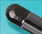
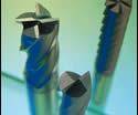
Ground Cubic Boron Nitride (CBN) ball end mills are the next generation tool for hard milling. An increase from 2800 Vickers to 4500 Vickers means a tool that can sustain five to 10 times the life of a TiAlN-coated carbide end mill. Advancements in grinding techniques have made it possible to grind spiral geometry from CBN (see Figure 2), which was once deemed impossible from the standpoint of accuracy due to the wheel's tendency to deflect during grinding. Now the same technology once only used with milling and turning insert technology is now available in the solid round tooling industry for finishing hardened steels up to 70 Rockwell-C. The result is lower long-run tooling costs, improved finishes and the elimination of tool change marks.
New Geometry (Low RPM Spindles, but Elevated Feedrates)
Old Way
Shops without high-speed spindles (15,000 to 40,000 rpm) are forced to sacrifice cycle time because they cannot generate the spindle speeds necessary to attain faster and more productive feedrates. The result is less productivity and an inability to compete with those shops bidding for the same work with faster spindles.
New Technology
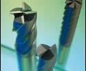
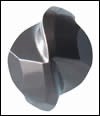
A new patented generation of cutting tools has been designed to allow for low speed/high-feed machining. The new design features a three-dimensional negative cutting angle that changes from slight to strong negative rake along the length of the cutting edge (see Figure 3).
This new evolution in design should not be confused with variable helix end mills that focus on harmonics to aid in machining. These new end mills have uniform helix angles and indexes, but change in terms of cutting angles to reduce cutting forces (load) and heat generation. The 3-D blended cutting edge essentially uses the concept of radial chip thinning, thereby producing a smaller chip and permitting more aggressive chip loads. The result of more flutes in combination with this design enables higher feedrates without the usual need for increased spindle speed capacity. It is designed for machines with adequate control technology (look-ahead software) and spindle speeds ranging from 4,000 to 12,000 rpm.
Another key advantage is the ability of this cutting form to maintain constant loads even when tool overhang is lengthened and greater left-over stock amounts are encountered. This capability means fewer tools will be required for semi-roughing and semi-finishing operations, which can equate to significant time and cost-savings when processing larger molds or dies. No longer must moldmakers with less than 15,000 rpm spindles be limited to lower metal removal rates.
New Geometry (Water-Line Processing for Mold Bases)
Old Way
Water lines for mold bases are typically processed using gun drills or carbide-tipped drills. Using high-pressure coolant, the drills are fed at very slow feedrates of 1 to 2 inches per minute with constant peck cycles to ensure chip evacuation. A 7/16” waterline 9 inches deep can take up to 90 seconds to drill completely using this process.
New Technology
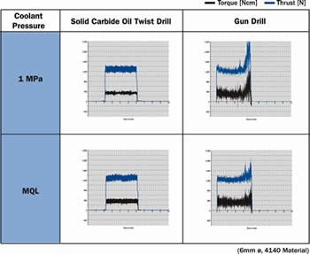
Solid carbide coolant-fed twist drills designed specifically for mold water-line processing can drill up to 30 times the diameter of the drill without pecking, at feedrates of 18 to 30 ipm—reducing cycle times from minutes to seconds. Furthermore, tool life is more predictable, finish is improved and accuracy is maintained within 0.001".
The new generation of carbide, coolant-through twist drills utilize tailored flute forms and point thinning to create small broken chips and smooth evacuation. The result is constant cutting torque from the top of the hole to the bottom (see Figure 4).
New Surface Treatments (50 HRC and above)
Old Way
Hardened die steels above 50 Rockwell-C are most frequently processed with carbide tools treated with TiAlN. To date many mold shops have been satisfied with the cutting tool technology available for hard milling. The best tools on the market typically permit hard milling in 60 Rockwell-C material up to 400 sfm. The constraint holding our industry back from going faster has always been the inability of the coating to sustain itself at any faster speeds due to the elevated levels of heat. As discussed in the aforementioned coatings summary, TiAlN has a thermal oxidation temperature of approximately 800oC. Beyond this temperature is where the coating breaks down and the tools inherently fail.
New Technology
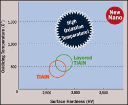
The advent of nano coating technology has brought about a new hybrid version of the multi-layered TiAlN coating. Nano coatings have transcended the barriers established by former versions of Titanium Aluminum Nitride. Nano technology yields a surface treatment with an increased oxidation temperature of 1350oC. In addition, it also has a higher surface hardness of 3600 Vickers (compared to the original 2800 Vickers of TiAlN, see Figure 5).
The advantage of such a technology is substantially higher spindle speeds in hardened steel because of an elevated sfm allowance. Increases in speed of 30 to 45 percent (525 sfm versus 400 sfm) over standard TiAlN translate to faster cycle times without sacrificing tool life.
Summary
Competition among moldmakers remains fierce in the U.S. While business has improved dramatically in comparison to three years ago, the fact remains that those who manage to stay ahead of the technology curve are the ones who will continue to thrive as our industry continues to redefine itself.
It is important to understand that tooling strategies once thought completely optimized should be reexamined to ensure it is not being done better somewhere else. The technologies reviewed in this article illustrate how minimal investments in new tooling technologies can yield dramatic increases in productivity, tool life, and most importantly, the bottom line.
Related Content
Questions and Considerations Before Sending Your Mold Out for Service
Communication is essential for proper polishing, hot runner manifold cleaning, mold repair, laser engraving and laser welding services.
Read MoreMMT Chats: 5 in 5 with Best Tool and Engineering
MoldMaking Technology Editorial Director Christina Fuges reveals 5 best practices for improving efficiencies within shops...in 5 minutes. Our guest is Joe Cherluck, President of Best Tool and Engineering in Clinton Township, Michigan.
Read MoreDynamic Tool Corporation – Creating the Team to Move Moldmaking Into the Future
For 40+ years, Dynamic Tool Corp. has offered precision tooling, emphasizing education, mentoring and innovation. The company is committed to excellence, integrity, safety and customer service, as well as inspiring growth and quality in manufacturing.
Read MoreWhat is Scientific Maintenance? Part 2
Part two of this three-part series explains specific data that toolrooms must collect, analyze and use to truly advance to a scientific maintenance culture where you can measure real data and drive decisions.
Read MoreRead Next
Advanced Cutting Tools Translate To Greater Cost Savings
Increasing initial tooling investments will allow moldmakers take home more profits at the end of the day.
Read MoreApplying cBN Technology to Moldmaking
A summary of cBN and its progression to a preferred substrate for high-accuracy hard milling.
Read MoreHow to Choose the Right Tool Coating for Your Machining Application
Selection criteria and common coating attributes for PVD, CVD and other common coatings.
Read More




.png;maxWidth=300;quality=90)


