Hot Runner Application Review Leads to Successful Processing
Successful application of a hot runner in the molding environment requires detailed analysis of gating styles, resin and molder expectations.
Hot runner systems are a key component of the multi-cavity injection mold. Ironically, hot runners are probably the least understood mold component from the moldmakers’ perspective. A hot runner is a complex system including mechanical actuation, heating technology and precision manu-facturing. Successful application of a hot runner in the molding environment requires detailed analysis of gating styles, cavity geometry, resin and molder expectations. A full-service hot runner sup-
plier can work with the mold designer, processor and part designer to ensure successful application of a hot runner.
Questions such as the following can be evaluated during initial application review.
- Can the part be molded?
- Does the molding machine have the pressure capacity to mold the part?
- Will the process be reliable for the entire mold run?
This review has proven to be a great benefit by predicting system performance and identifying potential problems for challenging applications.
Application Review
Application review involves three key steps: computer-aided engineering analysis, resin tests and hot runner concept design.
1. Computer-Aided Engineering (CAE) Analysis
Computer-aided engineering tools, such as MoldFlow™ analysis software, are used to analyze plastic flow in a molding system. These programs are often used by the mold designer to predict part fill pressures, flow lines, voids, shrinkage and warp.
It is best to apply computer-aided analysis on molding projects at the earliest stage possible. Even a crude analysis done at an early stage will answer some important questions such as probability of fill, cycle time, machine requirements and flowline prediction.
With the aid of computer engineering software, iterations can easily be performed to simulate different scenarios so that your cost and timing on later mold trials can be reduced to a minimum.
While the use of flow modeling programs for part analysis is popular, adding the hot runner manifold in the analysis has only recently become an option. Modeling the geometries of the manifold melt channels will result in more accurate predictions. Also, these software programs can be a great benefit when attempting to balance a family mold with multiple sized cavities.
1. Family mold
Family molds are used to make molding more economical when producing low-volume parts. Family molds generally consist of two or more parts of an assembly.
Ideally, the multiple parts in a family mold fill at the same time. Otherwise, when one part is full, other parts are either over packed or short. Traditionally, family molds are balanced by adjusting a cold runner diameter. Today, all of the parts of a family mold can be direct-gated with a balanced hot manifold design.
We were challenged to design a hot runner for a family mold that produces six parts of three very different designs. The parts vary from 49 grams to 171 grams. The left and right end three drops feed part “top” (qty 2, part weight 171g each), the middle two drops feed part “B” (qty 2, part weight 166g) and the remaining two drops feed part “A” (qty 2, part weight 49g each). The customer required that the largest part “top” must be flow balanced with lightest part “A”. The third part “B” could be adjusted by cold runner diameter. Without CAE tools this would require multiple and expensive iterations of the mold and gate design.
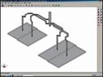
When balancing a family mold, the first step is to determine the ideal cavity pressure for each cavity. This is the pressure that you would expect if the part were molded by itself. We determined the cavity pressure difference between the smallest and largest part at the same fill time. The difference was quite significant (14,118 psi versus 23,112 psi) due to the thinwall sections (see Figure 1).
An added challenge to this application was that the customer required thermal gating options instead of valve gating. This eliminated the possibility of using sequential valve gating to balance flow. The system needed to achieve balance with melt channel diameter and flow length.
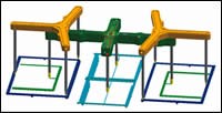
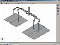
Using CAE tools the manifold melt channels and the cold runners were designed to achieve the best possible filling balance. A unique three manifold system was designed to meet the need of this family mold (see Figure 2).
2. Resin Test
Resin tests are used to evaluate the processability of a resin with a specific configuration of components. Resin tests can be performed when applications involve: resins with little or no hot runner processing history, specific gating or gate quality requirements, or have unique molding machine features or limitations.
The resin test is designed to evaluate the process window of the resin and component combination. The basic steps of the test are:
- Evaluate injection rates and corresponding pressures to determine optimum fill time for the test.
- Establish hot runner temperature window that will produce acceptable parts.
- Vary hold time and pressure in experimental fashion to determine the baseline for producing parts with best possible dimensions and gate quality.
- Evaluate resin’s sensitivity to residence time.
- Optimize each molding parameter to estimate total cycle time for the application.
In addition to the standard test procedures, custom tests can be performed to evaluate unique processing parameters or requirements.
Resin tests allow customers to obtain actual process data prior to the initial mold test and provide molded part samples before the design of the tool is complete.
3. Hot Runner Concept Design
Another important step is a hot runner design concept. A detailed design concept, including the manifold and plates, can be an important part in a mold review.
The manifold concept would be used to ensure that the melt channels can be laid out in the most efficient manner. Ideally, melt channels are designed in symmetrical patterns with both the flow length and number of turns being identical for all drops. In the case of family or non-symmetrical molds the melt channels may include artificial lengths and turns in order to properly balance the system. The concept will help both the mold designer and hot runner designer to ensure that the optimum manifold design can be used.
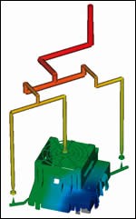
We were given the challenge of balancing plastic flow for weld line control on a part that required three gates. We were able to evaluate both the flow balance and manifold layout to ensure that the spacing of drops could meet the needs of the customer’s mold base through a detailed manifold design concept. The final result was a combination of single direct gate and two hot-to-cold gates on the single cavity (see Figure 3).
Additionally, a plate concept would be used to ensure the customer’s shut height and critical features can be designed. With the hot runner nozzle included in the nozzle, the mold designer can confirm that gate access and cooling meet the requirements of the hot runner manufacturer.
The main factors that can be evaluated during hot runner concept include:
- Optimum layout for flow balance and manifold thermal profile
- Channel size
- Manifold material strength evaluation in high pressure applications
- Gate size
- Cooling and gate access
- Components to withstand abrasive and corrosive resins
Summary
Hot runners are a complex and beneficial mold component. CAE analysis, resin tests and design concepts can all be performed by hot runner suppliers as partners in the mold program. By including the hot runner supplier in the early stages of a project the mold designer can optimize the final product and eliminate possible roadblocks.
Related Content
Four Micro Tooling Considerations
Issues involving gating, ejection, mold splits and direction of pull are of special concern when it comes to micro tooling.
Read MoreTolerancing in Mold Design, Part 1: Understanding the Issues of Conventional Bilateral Tolerancing
Mold designers must understand the location, orientation and form limitations of conventional tolerancing before changing to another dimensioning system.
Read MoreHow to Select a Mold Temperature Controller
White paper shares how cooling channel analysis, which collects maximum pressure drop, total flow rate and heat dissipation, eases the performance evaluation of mold temperature controllers.
Read MoreHow to Improve Your Current Efficiency Rate
An alternative approach to taking on more EDM-intensive work when technology and personnel investment is not an option.
Read MoreRead Next
How to Justify Your Hot Runner Purchase
Four questions to help with hot runner justification.
Read MoreFEA of Hot Runners to Optimize Mold Design
Optimization of a mold design with a hot runner system can be done with CAE simulations.
Read MoreSelecting the Right Gating Method for Your Application
Designers may select among four hot runner gating methods, each with its advantages and disadvantages.
Read More

